How do composite engineers accurately thermoform ROHACELL® PMI structural foam cores to tight tolerances? Successful thermoforming requires matching grade-specific temperatures between 165 °C and 230 °C, calculating soak times based on sheet thickness, and maintaining consolidation pressure until the core cools below 80 °C. At Chem-Craft, our technical team helps composite manufacturers manage these thermal cycles to produce dimensionally stable, repeatable sandwich structures.
What Is Thermoforming ROHACELL®?
Thermoforming ROHACELL® is the controlled process of heating a rigid sheet of polymethacrylimide (PMI) closed-cell foam until it becomes thermoelastic, shaping it against a mold, and cooling it under pressure so it retains the tool geometry. Unlike linear thermoplastics that melt into a fluid, PMI foam technology maintains its cellular matrix during heating. This allows the core to drape, stretch, and compress over complex contours while preserving its closed-cell integrity.
In lightweight composite structures, thermoformed foam cores replace heavy resin pockets and labor-intensive manual shaping typical of honeycomb or PUR foam cores. Forming the core to net shape before sandwich layup ensures seamless manufacturing process compatibility with prepreg autoclaves, resin transfer molding (RTM), and vacuum infusion.
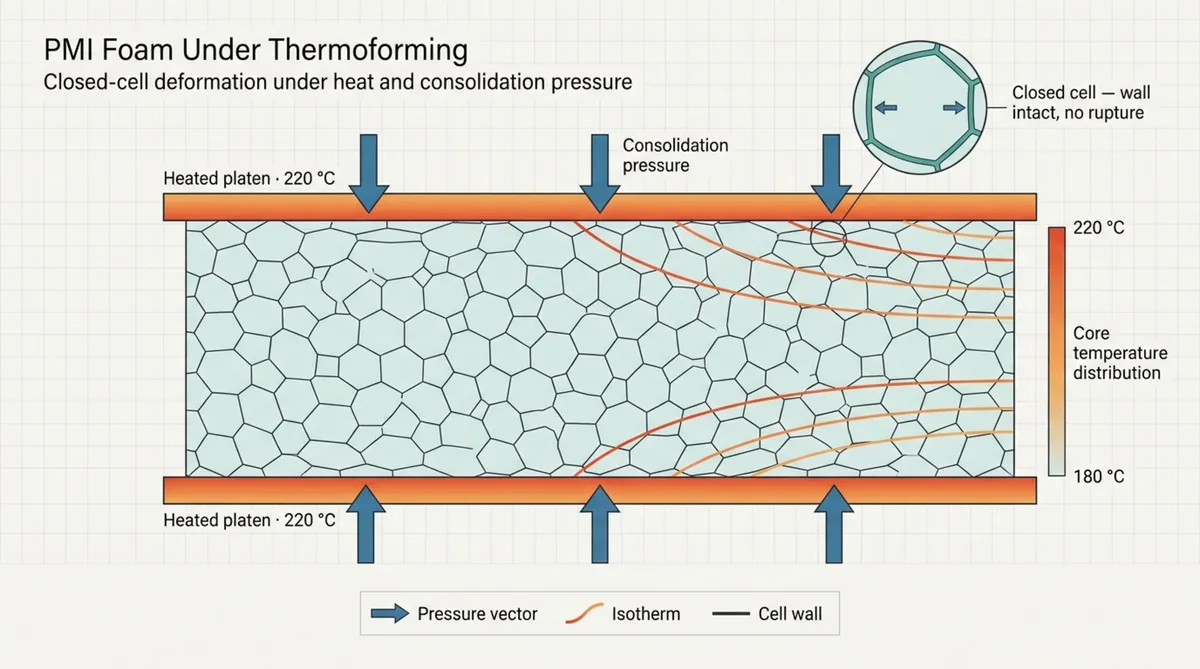
How ROHACELL® PMI Foam Responds to Heat and Pressure
At ambient temperatures, the methacrylic acid and methacrylonitrile copolymer matrix in ROHACELL® acts as a stiff, rigid solid. As the material absorbs heat and nears its glass transition region, its molecular bonds relax and shear modulus drops sharply. In this thermoelastic state, cell walls bend smoothly without rupture, allowing the foam to adapt to moderate draw depths and tight compound radii under controlled force.
You must balance the applied consolidation pressure carefully. Because each closed cell contains trapped gas, excessive mechanical pressure crushes the cell walls, causing permanent density increases and lost mechanical performance. Conversely, forming without sufficient consolidation pressure or exceeding the upper temperature limit allows the internal gas to expand, leading to blisters, cell rupture, and out-of-tolerance dimensions.
Which ROHACELL® Grade and Density Match the Part Design?
Selecting the right core depends on your operating environment, structural loads, and curing cycle parameters. General-purpose grades like ROHACELL® IG-F balance structural performance with cost efficiency in commercial and industrial composite applications. When manufacturing aerospace parts that require high-temperature autoclave cures alongside toughened epoxy or bismaleimide (BMI) resin systems, high-performance grades like ROHACELL® HERO, S, and ROHACELL® XT are engineered to withstand higher thermal and pressure demands.
Material density directly affects thermoforming behavior. Standard densities range from 31 kg/m³ to over 200 kg/m³. Lower-density grades have thinner cell walls and larger cell volumes, making them more sensitive to local shear cracking or buckling under steep draw angles. Higher-density grades offer superior compressive strength during mold closure, though their increased thermal mass requires longer heating soaks and greater forming forces.
What Temperature Is Required to Thermoform ROHACELL®?
The operational forming window for ROHACELL® lies between 165 °C and 230 °C, depending on the polymer cross-linking and specific grade. You cannot treat this range as universally interchangeable. Forming below the specific lower limit causes brittle cracking along outer radii, while exceeding the upper threshold triggers permanent thermal expansion and loss of original cell geometry.
The lower limit represents the minimum temperature at which the polymer softens enough to yield without fracturing. The upper limit is dictated by the thermal stability of the cell gas and polymer chains. Exceeding this boundary causes unrecoverable volume changes and ruins the mechanical integrity of the core.
Recommended Forming Temperature by ROHACELL® Grade
Polymer chemistry dictates the required thermoforming setpoints for each grade. Standard structural grades soften reliably between 190 °C and 205 °C. For instance, ROHACELL® WIND-F forms near 195 °C, standard ROHACELL® SL sheets form consistently at 200 °C, and ROHACELL® S typically requires 200 °C to 215 °C. Higher densities within these families often require processing near the top of their respective ranges.
Specialized high-temperature grades demand higher thermal inputs. ROHACELL® XT requires forming temperatures near 225 °C, while ROHACELL® XT-HT forms at approximately 230 °C. Attempting to bend these grades at a standard 180 °C window leads to immediate core cracking. Conversely, exposing standard grades to the high temperatures required for XT will degrade the cellular matrix.
How Core Temperature Differs from Oven or Tool Temperature
Because PMI foam is an exceptional thermal insulator, external oven readings do not indicate internal core readiness. In a circulating-air oven or under infrared heaters, the surface of a 30 mm sheet may register 210 °C while the internal core remains at 120 °C. Applying forming pressure at this point creates severe internal shear stresses, as the rigid center resists the stretching outer layers.
The tooling also influences thermal transfer upon initial contact. An unheated or insufficiently heated metal tool extracts heat rapidly from the contact surface, dropping the skin temperature below the thermoelastic window before the mold closes completely. You must monitor through-thickness core temperature directly rather than relying solely on ambient oven thermocouples.
Why the Manufacturer’s Grade-Specific Datasheet Takes Priority
Standard processing rules cannot account for every polymer modification, cell structure refinement, or density variation across product lots. Material specifications are continuously refined to improve resin absorption resistance and mechanical fatigue properties. For this reason, the processing instructions on the specific technical datasheet must serve as your baseline reference.
Assuming two grades with identical densities behave identically under heat introduces high process risk. The certified datasheet provides your definitive boundaries for thermoelastic behavior, allowable duration at temperature, and safe mechanical pressures.
How Long Does ROHACELL® Take to Heat and Form?
ROHACELL® cycle times depend directly on low thermal diffusivity. Unlike solid metals or unfoamed polymers that conduct heat rapidly, closed-cell PMI foam impedes heat flow. Achieving uniform temperature across the cross-section requires controlled heating rates and adequate soaking stages.
Every thermal forming cycle must begin with moisture removal. PMI foam naturally absorbs atmospheric humidity during storage and handling. If you heat a moisture-laden sheet directly to 200 °C, the water converts into pressurized steam inside the closed cells, causing blisters and cell rupture. Your thermal planning must account for a dedicated drying cycle prior to the forming ramp.
How Thickness, Density, and Part Size Determine Heating Time
In a circulating-air oven, a baseline rule of thumb is approximately one minute of soak time per millimeter of core thickness once the oven reaches its set temperature. However, this is only a starting estimate. For core thicknesses exceeding 25 mm, internal heat transfer slows significantly, requiring non-linear increases in soak time.
Density also changes the heating profile. A core at 110 kg/m³ contains substantially more solid polymer per unit volume than a 31 kg/m³ sheet. It demands higher total thermal energy to achieve an even thermoelastic state. Furthermore, sheets inside an oven must maintain at least 25 mm of spacing between them to guarantee unobstructed airflow across all surfaces.
How to Confirm Through-Thickness Temperature Before Forming
To ensure dimensional consistency, verify that the core center has reached the target forming temperature before initiating tool closure or vacuum draw. Relying solely on cycle timers exposes your process to inconsistencies caused by oven door cycles or shop-floor ambient shifts. Thermal profiling with embedded thermocouples provides reliable process control.
Composite engineers insert fine-wire thermocouples into small test holes drilled to the neutral axis of a sacrificial foam block. This witness core tracks the true thermal lag between the oven air and the internal foam. Once internal sensors show that the core center is within the forming range while the outer surfaces stay below the expansion limit, you can lock in the automated heating recipe.
Recommended Forming Time, Hold Time, and Cooling Time
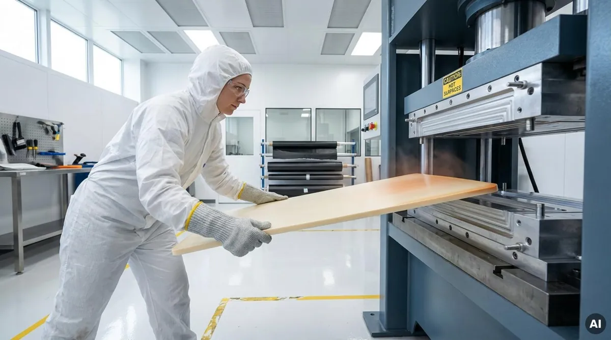
Once the sheet reaches target temperature throughout its thickness, transfer it to the forming tool quickly-ideally within 10 to 15 seconds. Unprotected foam skins cool rapidly upon exposure to room air. Using clean silicone sheets, breather fabrics, or thermal blankets shields the surface from heat loss during transfer.
The forming press or vacuum draw should stroke smoothly over 15 to 45 seconds, depending on geometric complexity. Once seated against the mold, maintain consolidation pressure continuously while the core cools. Hold the part under pressure until its internal temperature drops to 80 °C or lower. Opening tooling or releasing vacuum while the core exceeds 80 °C causes instantaneous springback and out-of-tolerance parts.
What Forming Pressure and Tool Conditions Does ROHACELL® Need?
ROHACELL® requires significantly lower consolidation pressures than solid composites or sheet metals. Because its closed-cell walls are microscopic, excessive force crushes the internal matrix. Depending on part geometry and core density, required forming pressure ranges from atmospheric vacuum consolidation (approximately 0.1 MPa) up to matched-die press forces between 0.3 and 0.7 MPa.
Tool design is vital to part quality. Whether utilizing female cavities under vacuum bagging, elastomeric pressure intensifiers, or precision-machined aluminum matched dies, the mold must support the foam evenly. Concentrated pressure peaks crush the foam locally, while insufficient contact force leads to bridging across inside corners.
How Tool Temperature Influences Surface Quality and Springback
Room-temperature tooling compromises dimensional stability. Placing a 210 °C sheet directly onto a 20 °C tool chills the contact surface instantly. This freezes internal stresses into the outer skin, creates surface wrinkling, and increases springback. When the surface hardens while the core remains malleable, differential cooling causes residual stresses that distort the final shape.
For high-precision applications, we recommend preheating matched tools to an intermediate range between 80 °C and 130 °C. Warm tooling keeps the foam skin pliable enough to capture tight radii and surface features without tearing. Controlled, symmetrical cooling from both tool faces minimizes internal thermal gradients and subsequent warpage.
How Radii, Draw Depth, and Clamping Affect Material Flow
Rigid foam cores do not stretch or shear like woven dry fabrics. ROHACELL® accommodates geometry through bending, elastic deformation, and localized inner-radius compression. Design rules dictate generous bend radii; using a radius smaller than twice the sheet thickness (2t) sharply increases the risk of tensile failure across the outer mold radius.
Deep-draw components require progressive blank control. Clamping sheet edges rigidly prevents natural material draw, causing excessive wall thinning and tearing at tool shoulders. Employing progressive vacuum stages or segmented pneumatic clamps allows the blank to feed inward gradually, preserving cell wall integrity along vertical sections.
Which Tolerances Can Thermoformed ROHACELL® Hold?
Establishing accurate manufacturing tolerances requires accounting for three distinct variables: baseline sheet thickness tolerances, thermal shrinkage during cooling, and mechanical tooling constraints.
Precision matched metal tooling regularly achieves profile tolerances of ±0.5 mm on moderate single- and compound-curvature parts. Complex geometries with deep draws, sharp transitions, or varying cross-sections are more demanding. These components often require 5-axis CNC-machined tools, active thermal management, and post-forming machining.
Dimensional Tolerance for Flat Panels and Complex Contours
For simple curves and aerodynamic fairings, thermoformed ROHACELL® holds surface profile tolerances of ±0.3 mm to ±0.5 mm when processed in matched dies. Using vacuum-bag forming against single-sided tools generally yields profile tolerances within ±0.8 mm of the CAD profile, provided the core has been thoroughly dried and cooled below 80 °C before debagging.
Complex multi-axis shapes with reverse curves or tight recesses exhibit wider tolerance bands. Localized draw differences and friction typically yield variations between ±1.0 mm and ±1.5 mm on uncompensated tools. For critical interfaces, Chem-Craft provides post-forming foam shape milling to restore final core profiles to strict engineering requirements.
Thickness, Density, and Compression Tolerances
Raw foam sheets carry baseline thickness tolerances that factor directly into your overall sandwich stack-up. Standard raw sheet tolerances range between ±0.2 mm and ±0.5 mm depending on thickness and surface finishing. When required, Chem-Craft provides precision horizontal cutting to deliver material thicknesses with tolerances down to ±0.1 mm.
Natural density variations within raw manufacturing blocks also impact forming behavior. Manufacturer specifications define acceptable production tolerance bands. For example, ROHACELL® IG-F grades exhibit permissible lot-to-lot density variations of roughly ±20% around nominal values:
| ROHACELL® Grade & Density | Nominal Density (kg/m³) | Allowable Density Range (kg/m³) | Nominal Density Spread |
|---|---|---|---|
| 31 IG-F | 32 | 25 – 39 | ±21.8% |
| 51 IG-F | 52 | 40 – 64 | ±23.0% |
| 71 IG-F | 75 | 60 – 90 | ±20.0% |
| 110 IG-F | 110 | 89 – 131 | ±19.1% |
High-density sections offer higher compressive resistance. If a single sheet exhibits density variations across its area, it will compress unevenly under identical mechanical press loads, altering the final thickness profile across the part.
How Springback and Thermal Shrinkage Affect Final Dimensions
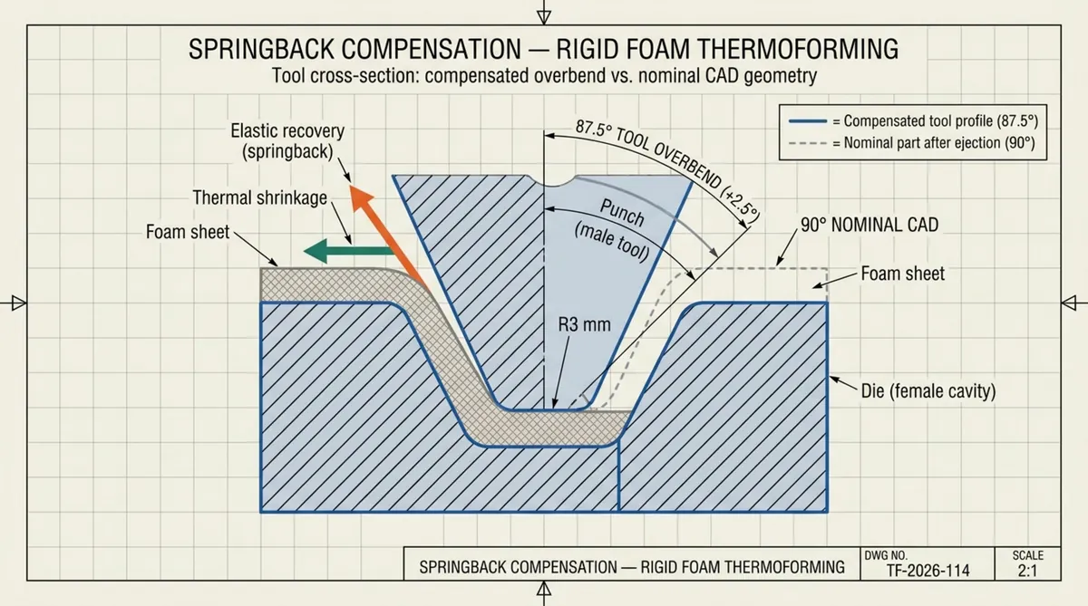
Thermoformed PMI cores contract as they cool from processing temperatures down to ambient factory levels. Final part dimensions are governed by two physical mechanisms: elastic springback and volume shrinkage.
Elastic springback represents the recovery of stored elastic strain within the cellular matrix upon pressure release. Demolding above 80 °C allows warm cells to recover partially, opening bend angles and distorting planned radii. Thermal shrinkage occurs due to the material’s coefficient of thermal expansion (CTE). As the core cools from above 200 °C to 20 °C, the entire component contracts along all axes. Asymmetric cooling rates across mold surfaces induce differential contraction, resulting in part warpage and edge curling.
Design Tools with Compensation for Springback
Achieving tight engineering tolerances on finished assemblies requires tool designers to build springback compensation directly into the mold face. If an engineering drawing specifies a 90-degree corner, cutting the tool to exactly 90 degrees typically yields an unconstrained part resting between 92 and 93 degrees after cooling.
Using finite element simulations and iterative prototype testing, mold makers intentionally overbend the tooling surface. Designing a mold with an 87- to 88-degree angle and a slightly tightened radius compensates for elastic recovery, allowing the cooled core to rest precisely at nominal CAD geometry. This compensation depends entirely on consistent process parameters; shifts in heating duration or demolding temperature will alter the springback angle.
What Defects Can Occur During ROHACELL® Thermoforming?
Thermoforming rigid foam cores requires rigorous process adherence. Because the material consists of an interconnected cellular lattice, out-of-spec temperatures or irregular pressures cause permanent structural and cosmetic defects. Identifying defect origins early helps stabilize production runs.
Defects generally fall into two categories: geometric non-conformance stemming from uneven heating or pressure gradients, and mechanical matrix failure caused by overheating or excessive tool force. Both degrade sandwich core integrity and result in part rejection.
Wrinkling, Bridging, and Incomplete Tool Contact
Wrinkling typically forms along the inside compression faces of tight concave sections or inside complex compound curves. When the foam is forced to compress beyond its elastic yield limit without sufficient through-thickness support, the inner skin buckles into visible ridges. Correcting this requires optimizing tool radii, modifying clamp pressure, or utilizing heated matched dies to compress ridges while the core is pliable.
Bridging occurs when applied forming pressures fail to overcome the core’s bending stiffness. The sheet bridges across interior tool corners, creating unbonded voids between the foam and the mold face. This defect occurs frequently in vacuum-bag operations if the core has not fully reached its thermoelastic state or if vacuum distribution is non-uniform across the tool perimeter.
Core Collapse, Cracking, and Surface Damage
Core collapse happens when applied forming pressures exceed the compressive strength of the foam at elevated temperatures. If a matched mold closes rapidly before core temperatures normalize, or if mechanical tonnage is set too high, cell walls buckle permanently. This leaves a crushed, thin cross-section with a hard, glassy feel that cannot support structural shear loads.
Tensile cracks form on the exterior tension face of bends when cold or inadequately soaked foam is forced over sharp profiles. Surface damage can also originate from residual core moisture. Absorbed moisture turns into steam during heating, breaking through cell walls and causing blisters, cratering, and open surface pits.
How Is Thermoformed ROHACELL® Inspected?
Quality inspection of formed PMI cores must evaluate exterior surface geometry and internal cellular health. A core that matches nominal profile dimensions remains scrap if its internal cell matrix has suffered crushing or shear tears. Manufacturing protocols incorporate dimensional metrology followed by visual and non-destructive testing (NDT).
Inspect parts only after they have cooled fully and stabilized under standardized conditions (23 °C ± 2 °C and 50% relative humidity). Inspecting cores immediately after demolding produces inaccurate dimensional data because the material is still undergoing thermal contraction.
Dimensional Inspection Against the CAD Model and Drawing
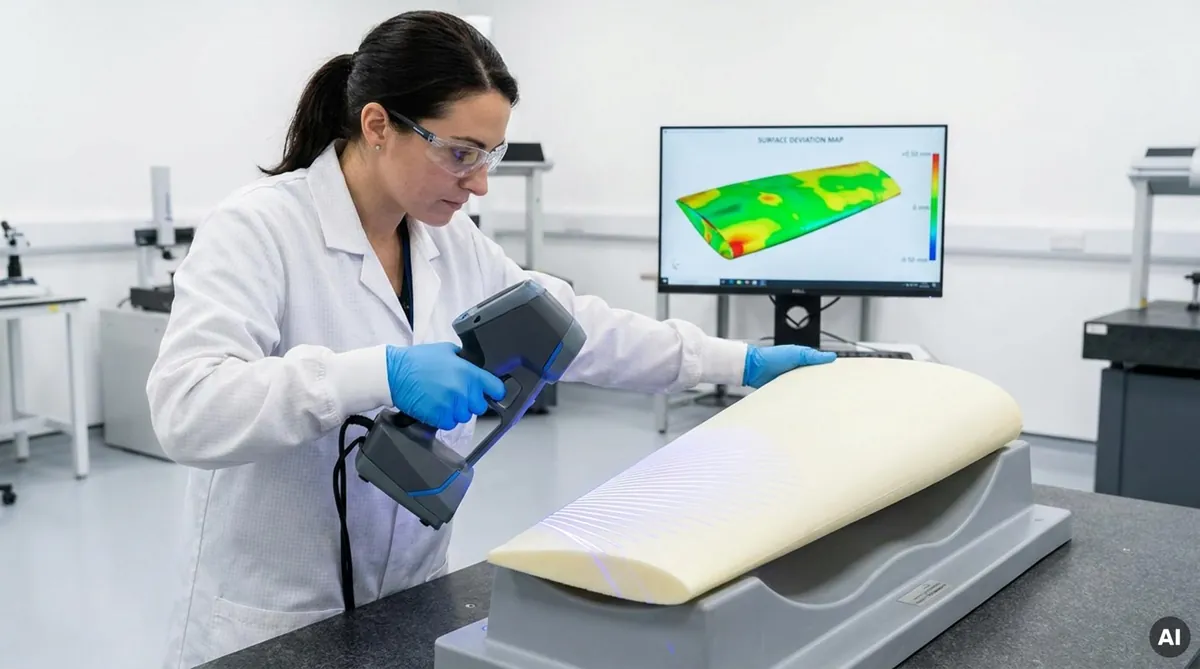
Quality inspection teams utilize laser scanners, structured-light optical systems, or low-force coordinate measuring machines (CMM) to verify complex formed geometries. The physical core is aligned to the 3D CAD model using a reference datum scheme (such as 3-2-1 alignment) to generate a full-field surface deviation heat map.
These optical scans confirm whether the core settled completely into corners and reveal the exact degree of edge curl or springback across broad spans. Ultrasonic thickness gauges calibrated for PMI foam should be used to map cross-sectional core thickness, verifying that localized stretching has not reduced core thickness below structural limits.
Visual Inspection for Cracks, Wrinkles, Voids, and Crushing
Visual inspection under high-angle directional lighting highlights surface anomalies that optical scans can overlook. Inspectors inspect curved radii for fine tensile micro-cracks, surface tears, and inner compression wrinkles. They also check for thermal degradation, which appears as dark discoloration, surface glazing, or steam-generated blisters.
Physical checks validate visual observations. Technicians use light tap testing across panels to detect internal voids, core separation, or localized cellular collapse. For mission-critical aerospace structures, low-frequency ultrasonic testing or X-ray computed tomography (CT) inspects the internal cell structure without damaging the formed component.
What Should a ROHACELL® Thermoforming Process Specification Include?
To eliminate process drift across manufacturing shifts and production batches, document every parameter within a formal Process Specification. Relying on undocumented machine adjustments results in scrap whenever material lots change or ambient shop humidity fluctuates.
This technical document serves as your definitive production guide. It standardizes receiving inspection, moisture removal cycles, tool preheating, thermal soak rates, transfer windows, demolding parameters, and quality sign-offs, establishing a stable baseline for aerospace-grade manufacturing.
Material Grade, Density, Sheet Thickness, and Initial Dimensions
The specification must define the raw material using complete product designations. General descriptions like “PMI foam” are unacceptable. The document must define exact chemistry, grade, nominal density, certified thickness, and manufacturer batch numbers for full traceability.
Record initial sheet cutting dimensions, edge prep, and orientation. If extra periphery material is required for vacuum sealing, mechanical clamping frames, or post-cure 5-axis edge trimming, include these dimensions alongside final net-trim limits.
Target Temperature Range and Maximum Exposure Temperature
Define operating windows with tight numerical boundaries rather than single setpoints. The process schedule should begin with mandatory low-temperature drying to drive out absorbed moisture. Standard drying cycles specify a holding temperature of 130 °C ± 5 °C for 4 to 12 hours depending on core thickness:
| Sheet Thickness Range (mm) | Drying Temperature (°C) | Minimum Soak Duration (Hours) | Process Objective |
|---|---|---|---|
| Under 25 mm | 130 ± 5 | 4 | Moisture removed; vapor pressure reduced |
| 25 to 50 mm | 130 ± 5 | 6 | Prevents cell expansion and steam blisters |
| 50 to 75 mm | 130 ± 5 | 8 | Stabilizes starting weight across thick cores |
| 70 to 100 mm | 130 ± 5 | 10 | Removes moisture from the center |
| Over 100 mm | 130 ± 5 | 12 | Balances moisture through the full section |
Following drying, define the hot-forming window. State the minimum core temperature required for thermoelastic shaping and the absolute maximum exposure temperature permitted before cell degradation begins. For example, a specification might mandate a target internal core temperature of 205 °C, with an absolute minimum of 200 °C and an absolute maximum of 215 °C. Any core exposed above the maximum limit must be quarantined immediately.
Heating Time, Forming Time, Hold Time, and Cooling Conditions
The final section of your Process Specification outlines machine kinematics and cycle timing. Specify whether the heating phase relies on timed oven recipes or internal core thermocouples. Set a strict limit on open-air transfer time-typically under 12 to 15 seconds-and mandate protective thermal blankets to prevent skin cooling during transfer.
Document tool preheat temperatures, mold closure speeds, and consolidation pressures. Mandate that consolidation pressure remain applied until internal temperatures drop to 80 °C or lower. Reheating an already formed core to correct geometry is prohibited, as repeated thermal cycles alter material tolerances. Cores that pass inspection proceed directly to trimming, milling, or sandwich panel layup.
Future Advancements in PMI Core Forming: Automation and Co-Cure Integration
As composite manufacturing rates rise across commercial aerospace, defense programs, and urban air mobility (eVTOL) platforms, thermoforming operations are evolving from manual batch steps into automated manufacturing cells. Previously, cores were thermoformed off-line, sealed in moisture-barrier bags, and positioned manually into tooling alongside prepreg skins. In advanced high-rate cells, robotic handling systems transfer pre-dried foam sheets through rapid infrared heating stations directly into automated forming presses, completing cycles within minutes.
This automated approach pairs with single-step co-curing. Rather than thermoforming the core as an isolated operation, modern production lines form pre-consolidated thermoplastic composite skins and the PMI foam core simultaneously in a single press stroke. The residual heat within the core and composite skins enables consolidation and direct fusion bonding without requiring secondary adhesive films. This eliminates processing steps, lowers consumable waste, and delivers fully consolidated sandwich structures ready for immediate airframe assembly.
If you need assistance selecting the right structural foam core or setting up thermoforming parameters for your manufacturing process, contact Chem-Craft’s technical team for engineering guidance.