How do machined structural foam cores support complex curved composite components? Multi-axis CNC machining shapes rigid foam blocks into precise compound profiles, preventing core buckling, wrinkling, and excess resin accumulation during infusion or autoclave processing. This approach provides a thermally stable structural core that maintains tight tolerances and ensures continuous load transfer across curved sandwich structures.
What Are Machined Foam Cores for Complex Curved Components?
Machined foam cores are rigid cellular materials cut to specific three-dimensional profiles using multi-axis CNC milling equipment. In modern composite manufacturing, these cores form the lightweight structural center of sandwich structures that feature compound curves across multiple axes.
By milling raw foam blocks into precise geometries with variable tapers, integrated steps, draft angles, and rebates, we bridge the gap between digital CAD surfaces and physical composite layups. The core transfers shear loads between the composite face sheets, enabling composite assemblies to achieve high bending stiffness and lightweight structural performance.
How a machined foam core shapes a composite sandwich panel
A composite sandwich construction functions like an I-beam. Thin, stiff face sheets act as flanges that carry tensile and compressive stresses, while the structural foam core serves as the web that separates the skins and resists shear loads. In curved components, a machined foam core defines the exact geometry of both the outer mold line (OML) and inner mold line (IML).
Because closed molding tools establish rigid external boundaries, the machined core dictates internal cavity tolerances. An accurately milled core distributes compaction pressure uniformly across the laminate during vacuum bagging, autoclave processing, or closed molding. This uniform pressure prevents localized resin pockets, eliminates dry fiber patches, and protects thin skins against micro-buckling and shear crimping under high bending loads.
Why complex curvature favors CNC-machined cores over flat stock
Standard flat foam sheets cannot conform to compound or anticlastic curves without physical deformation. Forcing flat, rigid foam over double-curved surfaces introduces residual stresses that cause cell fracture, edge lifting, and mechanical springback. This springback can distort the tool surface or puncture vacuum bags during consolidation.
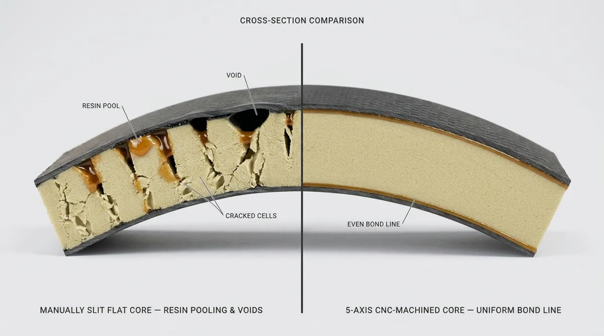
Slit, scored, or contour-cut foam blankets conform to moderate curves, but their open surface incisions draw in substantial quantities of laminating resin during processing. This excess resin increases structural weight without improving structural integrity. Five-axis CNC foam shape milling cuts compound profiles directly from solid foam blocks, allowing the core to seat perfectly against the mold without forced bending stresses or parasitic resin weight.
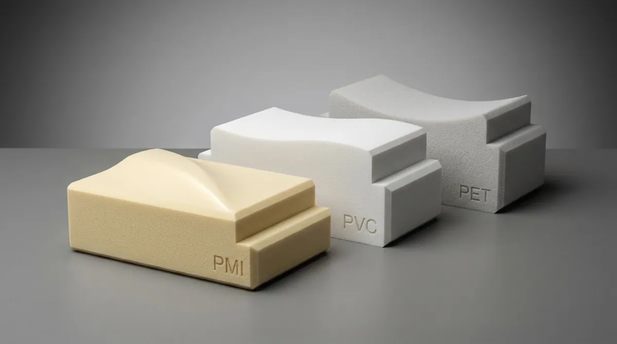
Typical materials: PVC, PET, PMI, polyurethane, and epoxy tooling foam
Core material selection depends on service temperatures, resin chemistry, shear modulus, and target weight limits. The primary foam categories provide distinct performance characteristics for curved composite manufacturing:
- Cross-linked Rigid PVC: Supplied in densities from 45 to 250 kg/m³. PVC offers balanced strength-to-weight performance, low water absorption, and acceptable fatigue life, making it common in marine hulls, railcar panels, and wind energy structures.
- PET (Polyethylene Terephthalate): A thermoplastic core material with service capabilities up to 150°C. PET offers recyclability, compatibility with standard resin infusion processes, and consistent impact performance for industrial and transit applications.
- PMI (Polymethacrylimide): A high-performance rigid foam widely specified in aerospace, defense, and high-end automotive applications. PMI foam technology, exemplified by ROHACELL® RIMA and ROHACELL® WF, delivers the highest specific shear strength, exceptional compressive creep resistance, and stable performance during autoclave processing up to 180°C at pressures reaching 0.7 MPa. Its fine cell structure supports clean CNC machining with clean edge retention.
- Polyurethane (PU) and Polyisocyanurate (PIR): Primarily used for thermal insulation panels, marine flotation compartments, and low-cost prototyping. These materials provide moderate mechanical strength and exhibit compatibility with polyester and vinyl ester resins.
- Syntactic and Epoxy Tooling Foams: High-density, microsphere-filled media utilized in subsea buoyancy modules, master models, high-pressure matched tooling, and localized structural hard points requiring compressive strength exceeding 20 MPa.
Why Foam Cores Improve Complex Composite Components
Integrating a machined foam core into a curved composite design alters how the structure supports operational loads. Instead of relying on thick, heavy solid laminates reinforced by complex rib arrangements, engineers can develop monocoque or semi-monocoque sandwich structures that distribute dynamic stresses evenly across contoured geometries.
Structural foam cores also deliver functional advantages, including acoustic damping, vibration mitigation, thermal insulation, and energy absorption during impact events. These properties provide distinct benefits across aerospace vehicles, passenger transit, and industrial equipment.
Increases bending stiffness without adding solid-laminate weight
Solid carbon-fiber or fiberglass laminates require numerous plies to achieve high out-of-plane stiffness, resulting in heavy and costly assemblies. Bending stiffness increases proportionally to the cube of total panel thickness. By introducing a low-density machined foam core that expands section thickness, engineers multiply panel stiffness while adding minimal weight.
This decoupling of section thickness from laminate mass enables variable core thickness across the part. We can machine thick cross-sections into high-load regions to minimize deflection, transitioning smoothly down to thin edges or solid laminate flanges at perimeter joints without mechanical fasteners.
Reduces hand layup work, filler use, and assembly time
Fabricating curved parts using separate stringers, bulkheads, and shear webs requires intensive manual labor. Technicians must step plies down, apply heavy bonding pastes, and manage secondary adhesive joints that introduce risks of peel failure and debonding.
A single, monolithic CNC-machined foam core replaces multiple hand-fitted details and secondary stiffeners. The pre-machined core drops directly into the mold cavity, matching the planned geometry and eliminating the need for fairing compounds or structural syntactic putties that add excess mass and introduce thermal variations during cure.
Supports repeatable geometry across prototypes and production parts
Hand-cut or manually formed foam cores introduce dimensional variations, resin content shifts, and uneven bond lines between production runs. These variations complicate downstream assembly and compromise structural calculations.
Direct CNC machining from 3D CAD master models ensures dimensional repeatability with tolerances as tight as ±0.1 mm, and up to ±0.05 mm for specialized applications. Whether producing initial prototypes or high-rate production runs, multi-axis machining maintains consistent internal mold lines, controlled bond-line thicknesses, and reliable assembly interfaces.
Where Are Machined Foam Cores Used?
Multi-axis CNC routing combined with high-performance structural foam cores serves industries requiring aerodynamic efficiency, minimal structural weight, and extended fatigue life. Wherever fluid dynamics or space limitations require complex curved geometries, machined cores provide internal structural stability.
Applications range from commercial aircraft components exposed to cyclical flight loads to deep-sea vessels subjected to hydrostatic pressure.
Aerospace, UAV, and aircraft interior components
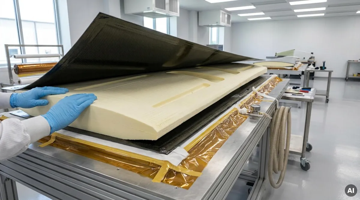
In aerospace structures, mass reduction directly improves payload capacity, fuel efficiency, and flight range. Machined PMI foam cores are standard in wing leading edges, control surfaces, engine nacelles, helicopter rotor blades, and space launch vehicle fairings.
Radomes require specialized materials such as ROHACELL® HF, which combines thermoforming and machining precision with a dielectric constant closely matched to air. This ensures radar and 5G communication signals pass through with minimal loss. In cabin interiors, flame-retardant machined foam cores form curved overhead bins, structural galleys, and environmental control system ducts compliant with aviation safety standards.
Automotive body panels, aerodynamic parts, and interior structures
Motorsport programs and commercial vehicle manufacturers utilize machined foam cores for aerodynamic diffusers, front splitters, contoured roof panels, and structural chassis tubs. Structural exterior components demand Class-A surface finishes; dimensionally stable machined PMI cores prevent the surface print-through and waviness often caused by slotted or draped core blankets.
Within electric vehicle structures, structural foam cores perform dual functions as lightweight crash-energy management elements and thermal barriers, featuring thermal conductivity values around 0.03 W/mK to preserve battery efficiency across broad operating temperatures.
Marine hulls, decks, and curved superstructure panels
High-performance vessels, naval craft, and passenger ferries employ complex hydrodynamic hulls and curved wheelhouses. Forcing sheet foam into deep bow sections or flared transoms creates voids that invite delamination under continuous wave impact.
Precision-machined closed-cell foam kits eliminate these structural weaknesses. Hull panels and deck assemblies are nested digitally and machined for direct placement during resin infusion. Closed-cell architectures certified by DNV prevent moisture ingress, preserving long-term structural integrity in demanding marine environments.
Wind-energy blades and industrial equipment housings
Modern wind turbine blades feature aerodynamic profiles with continuous chord twists along their span. Machined PET and specialized PMI foam cores form the internal shear webs and aerodynamic shell structures, preventing buckling under extreme wind gusts while resisting fatigue over millions of operational load cycles.
In industrial equipment, precision-machined foam sandwich panels provide stiff, lightweight enclosures for robotic automation arms and medical diagnostic equipment, such as X-ray and CT patient tables, where low beam absorption and high mechanical stability are required.
What Geometries Can CNC-Machined Foam Cores Produce?
Multi-axis CNC machining centers translate complex digital CAD surfaces into physical foam parts. Because structural foams produce low cutting resistance, high-speed machine spindles can generate complex surface contours and fine functional details with high efficiency.
Machining generates smooth organic surfaces, functional rebates, and variable wall sections, converting the foam core into a fully integrated structural component.
Double curvature and compound surfaces
Simultaneous five-axis milling produces continuous compound contours, including synclastic dome configurations and anticlastic saddle shapes, from single foam blocks. Ball-nose and bull-nose cutting tools track CAD surfaces to blend surface paths into smooth aerodynamic contours.
This precision allows the core to seat flush against tool surfaces, preventing bridging and edge liftoff during vacuum consolidation. The resulting composite sandwich maintains a uniform adhesive bond line without heavy, resin-rich areas.
Controlled radii and sharp-corner transitions
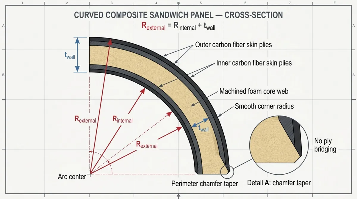
Structural reinforcing fabrics resist tight internal radii. CNC machining shapes exact, gradual radii into the foam core to match the natural drape of dry fabrics and prepregs, preventing ply bridging and dry fiber channels.
To ensure consistent laminate consolidation around a curve, core geometry follows this fundamental engineering relationship:
Rexternal = Rinternal + twall
Machining this relationship directly into the foam ensures uniform ply consolidation without pinching fibers at the curve apex or causing laminate bridging under vacuum pressure.
Deep draws, variable thicknesses, and tapered sections
Deep-draw components risk fiber misalignment and resin pooling if draft angles and step heights are poorly configured. Multi-axis CNC milling cuts steep, deep features in a single setup, applying precise draft angles to support laminate compaction and tool release.
Core thickness can also transition smoothly across a single component. A core may taper from a 50 mm central section down to a 2 mm feather edge at perimeter landing zones, preventing the stress concentrations associated with abrupt cross-sectional steps.
Undercuts and when split-core construction is required
Features such as internal return flanges, joggle details, or reverse drafts create die-lock conditions that prevent demolding a monolithic core from single-piece tooling.
In these cases, we design multi-piece split-core assemblies. The separate foam components are machined with interlocking puzzle joints, alignment tongues, or locating keys. Technicians assemble these sections within the mold cavity during dry-fiber lay-up or prepreg kitting, establishing a continuous internal structure that meets the extraction requirements of the tool.
How Core Material Properties Affect Curved-Part Performance
In a composite sandwich structure, face skins and core materials function as an integrated structural system. Treating the core merely as a geometric spacer can lead to overweight components, excess resin consumption, and performance shortfalls relative to FEA projections.
Engineers must evaluate density alongside compressive strength, shear modulus, thermal stability, and closed-cell integrity under active processing temperatures and consolidation pressures.
| Foam Material | Typical Density Range (kg/m³) | Cure Temp Capability (°C) | Key Performance Attributes | Common Structural Applications |
|---|---|---|---|---|
| Cross-linked PVC | 45 – 250 | Up to 90 (standard) / 120 (HT) | High shear elongation, fatigue resistance, low resin absorption | Marine hulls, wind blades, rail fairings, radomes |
| PET Foam | 65 – 320 | Up to 150 | Thermally stable, recyclable, impact toughness, weldable | Wind shear webs, automotive panels, transit floors |
| PMI Foam | 30 – 300 | Up to 180 – 205 | Highest specific strength, autoclave creep resistant, microcellular | Aerospace flight structures, motorsport tubs, helicopter blades |
| Rigid Polyurethane | 35 – 400 | Up to 100 – 110 | Thermal insulation, chemical resistance, cost efficiency | Insulated truck bodies, buoyancy modules, industrial covers |
Density selection: balancing stiffness, strength, weight, and cost
Structural foam densities range from 30 kg/m³ to over 250 kg/m³. Lower-density formulations (30 to 60 kg/m³) minimize overall weight and provide thermal insulation, making them suitable for non-critical fairings and broad aerodynamic covers. However, they exhibit lower shear strength and require careful handling around tight radii.
Mid-range densities (75 to 110 kg/m³) are standard in commercial marine, rail, and primary automotive components, balancing shear transfer, impact resistance, and machining efficiency. High-density grades (130 to 250 kg/m³ and higher) are selected for load introduction zones, edge closeouts, and structural bolting points, holding fine machined details and localized hardware pockets without cell wall collapse.
Compression strength, shear strength, and fatigue resistance
Under out-of-plane flexure, the core absorbs transverse shear stresses while resisting compressive forces applied by aerodynamic loads or mechanical clamping. Insufficient core shear strength leads to horizontal shear failure along the neutral axis, driving rapid skin-to-core debonding.
Dynamic fatigue resistance is essential in operational environments subject to cyclic loading, such as marine hull bottoms or wind turbine blade structures. Ductile core materials such as cross-linked PVC and high-performance PET withstand shear strain prior to yielding, slowing fatigue crack growth across high-stress zones.
Temperature resistance for curing and service conditions
Exceeding a core’s heat deflection limit during processing causes compressive creep and core collapse under vacuum or autoclave pressures. Standard PVC foams soften between 80°C and 90°C; applying an unconditioned standard PVC core to a 120°C epoxy prepreg cure will compromise the internal sandwich structure.
Elevated cure temperatures require foams engineered for thermal stability. Specialized PET cores tolerate cycles up to 150°C, while PMI structural foams support autoclave processing cycles up to 180°C at pressures of 0.7 MPa. For demanding cure profiles, thermal conditioning protocols-such as pre-drying at 135°C followed by controlled heat treatment at 150°C to 180°C-optimize creep resistance before final net-shape machining.
Closed-cell content, resin uptake, and water absorption
Cell morphology directly influences resin uptake during composite lay-up and moisture resistance during field service. High-performance structural foams maintain closed-cell contents exceeding 95% to 98%. Machining opens only the surface cells, which fill with resin to create a clean mechanical interlock with the face skins.
Microcellular foams, such as high-grade PMI, exhibit negligible resin absorption into deeper cell walls. Conversely, coarse-cell foams can absorb excessive resin during liquid infusion processes. On large structures like boat hulls or wind blade panels, this parasitic resin uptake adds substantial unintended weight and drives up production costs. Low moisture absorption also prevents freeze-thaw degradation if skins suffer impact damage in service.
How Core Design Supports Laminate Continuity
A properly machined core provides a smooth, continuous substrate for structural reinforcement plies. Abrupt geometric steps or sharp angles interrupt fiber paths, inducing bridging, unbonded voids, and resin-rich pockets that crack under fatigue loading.
Core engineering must account for fabric weight, drape characteristics, and planned stress vectors, ensuring core tapers and cutouts align with structural load paths.
Ply buildups, local reinforcements, and load-introduction zones
Primary composite structures frequently require local laminate buildups around load points, hinge fittings, and spar attachments. Placing these extra plies over an unmodified core creates outward bumps that distort external aerodynamic surfaces.
To maintain flush outer mold lines, multi-axis CNC routers machine recessed pockets directly into the core face. These ply-drop pockets accommodate localized reinforcements, allowing additional plies to sit flush within the sandwich while keeping the outer structural fibers aligned with the planned load path.
Core tapers and transitions that prevent hard spots
Abrupt steps in core thickness generate localized stress concentrations, leading to core shear failure or skin peeling during cyclic bending. Foam perimeters must taper gradually into monolithic laminate edges or adjacent inserts.
Standard composite design utilizes core chamfer ratios between 1:3 and 1:4 for general structural panels, while flight-critical aerospace structures often require shallow tapers ranging from 1:10 to 1:20:
Chamfer Ratio = Height : Run (e.g., a 1 mm thickness drop across a 4 mm length)
Machining precise chamfer angles enables continuous fiber contact without kinking, preserving load transfer across thickness transitions.
Radii that reduce bridging, wrinkling, and resin-rich areas
Heavy multiaxial and unidirectional fabrics resist tight bending due to inter-fiber friction. Applying fabric over an internal corner radius under 3 mm frequently causes ply bridging, where vacuum pressure pulls fibers away from the corner apex, creating an internal void.
During resin infusion, this void fills with neat resin, creating an unreinforced pocket subject to micro-cracking from thermal shrinkage. Machining generous, gradual radii on both internal and external core corners keeps fabric plies firmly seated against the foam, eliminating resin pooling and ply wrinkling.
Cutouts, inserts, channels, and embedded hardware locations
Point loads from mechanical fasteners can crush low-density core materials. Tightening a structural bolt through low-density foam will compress the cell structure and separate the skin from the core. CNC machining prepares precise pockets for high-density foam blocks, metal hard points, or solid syntactic inserts prior to skin lamination.
Complex sandwich assemblies can also feature integrated internal resin distribution channels or conduit pathways. Milling these features into the foam during core fabrication avoids secondary drilling operations and simplifies composite assembly.
How CNC Machining Controls Core Accuracy
Transforming low-density, flexible foam slabs into tight-tolerance 3D structural cores requires specialized machining parameters. Structural foams exhibit low thermal conductivity and delicate cell structures, requiring high spindle speeds, high-shear cutting tools, and robust vacuum holding fixtures.
An integrated digital-to-physical workflow-linking CAD design, CAM programming, multi-axis routing, and non-contact inspection-ensures the core matches composite mold dimensions precisely.
CAD-to-CAM workflows for complex curved components
The manufacturing sequence begins in CAD. Engineers derive the core volume by offsetting the outer mold surface by the exact cured ply thickness (CPT) of the composite skin. CAM programmers then develop simultaneous five-axis surface paths that keep the cutting tool oriented to the surface normal across compound curves.
CAM strategies must account for foam flexibility. Aggressive feed rates paired with dull tools exert lateral force that deflects the foam rather than slicing it, causing dimensional springback once tool pressure releases. Advanced CAM post-processors verify tool clearances, rotary table limits, and machine head envelope boundaries inside deep molds to prevent machine collisions.
Dimensional tolerances, surface finish, and thickness control
Dimensional control is critical in structural core manufacturing. High-performance composite assemblies demand thickness tolerances of ±0.2 mm to ±0.5 mm, with specialized flat dimensions achieved down to ±0.05 mm. An oversized core causes high tool-closing forces that crush cellular structures, while an undersized core causes vacuum bag bridging, resulting in dry fibers and poor laminate consolidation.
Surface quality is equally vital. High-speed cutters must slice cell walls cleanly rather than tearing them out. Shredded or damaged foam surfaces exhibit increased resin absorption, higher panel weight, and reduced flatwise tensile bonding strength.
Toolpath selection for thin walls, small radii, and deep features
Thin edges, narrow ribs, and deep pockets require dedicated cutting strategies. High-speed steel (HSS) and diamond-like carbon (DLC)-coated end mills with high positive rake angles slice through cell walls cleanly, minimizing frictional heat buildup and cell melting.
For fine edges and tall walls, programmers apply climb-milling strategies using light step-overs and high surface speeds to minimize cutting deflection. Deep-draw sections utilize high-helix roughing tools and specialized lollipop cutters to evacuate foam dust while avoiding tool chatter.
Inspection with templates, probing, scanning, or CMM measurement
Measuring low-density curved foam components presents unique inspection challenges. Standard touch-trigger CMM probes and physical calipers can compress soft foam surfaces, resulting in false dimensional measurements.
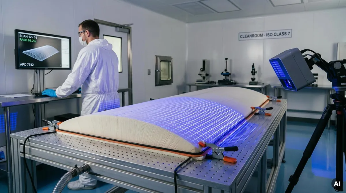
To ensure measurement accuracy, we utilize non-contact 3D optical scanning, blue-light digitizing systems, and laser tracking. Optical scanners capture dense point clouds of the free-state and vacuum-held core, comparing the physical component to the nominal CAD file to produce full-field color deviation maps that confirm profile accuracy prior to cleanroom delivery.
What Assembly Details Should Be Specified Before Machining?
A machined foam core must integrate cleanly into the downstream composite manufacturing process. Defining assembly parameters during the initial engineering phase prevents cleanroom delays, vacuum bag punctures, and alignment errors during lay-up.
Interface and clearance requirements between core sections
Large sandwich assemblies-such as marine hulls, railcar fairings, or large radomes-often require segmented core kits due to raw foam block sizes or CNC envelope boundaries. Mating clearances must be defined in advance.
Zero-clearance butt joints can overlap under thermal expansion or tool compression, puncturing the vacuum bag. Conversely, excessive gaps accumulate heavy pools of unreinforced resin. We recommend designing uniform gaps of 0.5 mm to 1.5 mm, which are filled during lay-up with structural core adhesives, syntactic paste, or expanding epoxy films.
B-side surfaces, tool-side references, and datum features
In single-sided molding processes, including vacuum infusion and wet lay-up, the tool-facing side of the laminate defines the primary surface, while the B-side contacts the vacuum bag. The B-side surface of the core requires smooth transitions to avoid tearing the bagging film under full vacuum.
Machined cores should include physical datum features that align with indexing points on the composite tool. CNC-milled registration notches, perimeter reference lines, and pin holes enable rapid, precise positioning by lay-up technicians without manual measurement.
Parting lines, registration features, and split-core alignment
When negative drafts or deep undercut sections demand a split-core design, interlocking features must be incorporated into the initial CAD model. Machined shiplap joints, tongue-and-groove connections, and stepped puzzle joints maintain core alignment under vacuum pressure.
These interlocking features prevent relative movement between core segments during liquid resin injection in RTM molds milling and closed-mold processing cycles.
Which Manufacturing Processes Pair with Machined Foam Cores?
Machined foam cores are compatible with nearly all standard composite manufacturing processes. Because each process introduces distinct thermal, pressure, and resin-flow parameters, core properties must be matched to the selected production method.
Prepreg and autoclave molding
Autoclave processing represents a demanding production environment for sandwich structures. Cure temperatures typically range from 120°C to 180°C, with autoclave pressures between 0.3 and 0.7 MPa. Standard foam materials can suffer compressive creep under these conditions.
PMI foams, such as ROHACELL® XT, are engineered specifically for high-temperature autoclave cycles. Technicians apply structural film adhesives between the machined core and uncured carbon-fiber prepreg plies. The foam core retains its compressive modulus throughout the cure cycle, maintaining the outer mold line without cell collapse.
Vacuum infusion and resin transfer molding
Liquid molding processes, including VARTM and RTM, pull liquid resin through dry fabric packs using vacuum pressure or positive injection. In these systems, the machined core can serve as both a structural core and an active resin distribution medium.
Machining shallow distribution channels (typically 1-2 mm wide by 1-2 mm deep) and through-thickness perforations directly into the foam facilitates balanced resin flow to both top and bottom skins simultaneously. This approach reduces fill times, ensures complete fiber wet-out, and eliminates disposable external flow mesh.
Wet layup, compression molding, and out-of-autoclave curing
For prototypes and low-volume production, wet lay-up followed by out-of-autoclave (OOA) vacuum bagging provides a practical manufacturing route. Machined cores place directly onto wet fiber plies, ensuring consistent geometry without matched composite tooling.
For high-rate manufacturing, matched-die compression molding utilizes rigid metal tooling to consolidate prepreg charges or wet mats against a machined core. The foam must withstand rapid press closure and localized pressure peaks without cracking or shifting within the tool cavity.
What Risks Can Reduce Core and Part Quality?
While machined foam cores enable high structural efficiency, process mismatches can compromise part quality. Recognizing how heat, pressure, and cutting mechanics interact with cellular foam prevents scrap and field failures.
Core crush, distortion, and springback during layup
Core crushing occurs when processing pressures exceed the compressive yield strength of the foam at the active cure temperature. In an autoclave, this leads to thickness loss and skin wrinkling. Tapered perimeter chamfers are particularly susceptible to lateral crushing forces from the vacuum bag.
Mechanical springback represents another processing risk. Clamping stresses induced during CNC milling can remain trapped in the foam. Once released from the vacuum bed, the core may curl slightly. Forcing a distorted core into the tool can cause it to lift off the mold face during resin gelation, leaving dry spots and surface defects.
Bridging over tight radii and compound curvature
Bridging occurs when an internal core radius is cut too sharp for the fabric to conform, or when the core does not seat completely in the tool. Under vacuum pressure, reinforcement fabrics span across the corner, leaving an unreinforced gap at the radius root.
During resin infusion, this void fills with liquid resin, resulting in heavy, unreinforced resin pockets that generate high exotherm temperatures during cure and act as initiation sites for fatigue cracking.
Excess resin absorption and void formation
Dull or incorrect cutting tools tear open subsurface foam cells rather than shearing them cleanly. This damaged surface functions like an open sponge, absorbing excess resin during infusion and adding unplanned weight to the final structure.
Conversely, poorly engineered resin flow channels or incorrectly spaced drill holes can trap air pockets during liquid molding, resulting in interfacial dry voids that weaken the bond between the face sheet and the core.
Mismatched cure temperatures and dimensional shrinkage
Polymer foam cores possess a higher coefficient of thermal expansion (CTE) than carbon-fiber or glass-fiber reinforcements. At cure temperatures between 120°C and 180°C, the core expands at a higher rate than the consolidating skins. As the part cools, the core contracts against the rigid laminates.
This differential contraction induces internal residual stresses, causing warpage or twisting once the part is demolded. Tool designers mitigate this risk by applying thermal compensation factors in CAD models and controlling autoclave cooling rates.
What Should a Machined Foam Core Specification Include?
A comprehensive engineering specification prevents misunderstandings between design teams and CNC foam processing partners. Generic descriptions such as “10 mm foam core” introduce ambiguity into production.
The manufacturing package must clearly define geometric tolerances, raw material grades, thermal parameters, and quality assurance protocols prior to production.
3D CAD model, drawings, datums, and allowable tolerances
The specification package requires a clean, solid 3D CAD model provided in native or neutral formats (STEP, IGES), representing the finished core geometry. This model must be accompanied by a 2D drawing applying Geometric Dimensioning and Tolerancing (GD&T).
Drawings should define thickness tolerances (such as ±0.2 mm), surface profile limits, chamfer angles, and datum schemes aligned with the physical composite tool. Separating critical aerodynamic interfaces from non-critical clearance regions helps balance machining efficiency with structural accuracy.
Foam type, density range, thickness, and cell structure
Specifications must state the explicit foam family (e.g., PMI, cross-linked PVC, PET) along with the specific product grade, nominal density, and acceptable density variation (such as 75 kg/m³ ± 5%).
Specifying the exact manufacturer grade prevents unauthorized substitutions. For weight-critical parts, the document should also define cell size requirements and a minimum closed-cell content of 95% to control resin uptake.
Cure cycle, operating temperature, and environmental exposure
The core specification must outline the maximum manufacturing parameters the foam will encounter, including peak cure temperatures, ramp rates, hold durations, and autoclave pressures. This data determines whether the raw foam requires drying or thermal conditioning prior to milling.
Operational conditions should also be documented, including continuous service temperatures, contact with aviation fuels or hydraulic fluids, and exposure to moisture. These factors confirm compliance with required flammability, toxicity, or marine classification standards.
Laminate schedule, load cases, inserts, and transition details
Providing laminate details helps the core manufacturing team anticipate processing challenges. The cured ply thickness (CPT) of the inner skin is necessary to calculate accurate core offsets. Fiber orientations also matter, as rough core surfaces can catch unidirectional fibers during lay-up.
Drawings must detail all embedded hard points, potted inserts, fastener locations, and edge tapers. Knowing high-stress load paths ensures that core segment seams and puzzle joints are positioned away from primary load vectors.
Inspection records, traceability, certifications, and packaging
Regulated aerospace, defense, and maritime programs require comprehensive material traceability. Specifications must identify required documentation, including raw material batch certificates, certificates of analysis (CoA), and optical scan reports.
Packaging protocols are equally important. Thin, tapered edges on curved foam cores are easily damaged during transit. Specifications should require protective shipping fixtures, support bucks, and heat-sealed aluminum barrier bags to protect dried foam cores from atmospheric moisture absorption.
How Should You Select a Machined Foam Core Supplier?
Machining complex 3D structural foam cores requires specialized machine setups, high-shear tooling, and custom vacuum workholding that differ significantly from standard metalworking practices. Selecting an inexperienced supplier risks cell wall damage, high resin absorption, and dimensional errors.
A qualified partner must combine multi-axis CNC routing capacity with deep practical knowledge of composite lay-up, infusion, and autoclave curing processes.
Reviewing experience with compound-curved composite components
Machining curved cellular foam requires an understanding of how composite fabrics drape and consolidate against core geometries. An experienced supplier understands how cutter tear-out increases resin weight, why corner radii influence fabric bridging, and how core offsets correspond to cured ply thickness.
Evaluate potential partners based on previous work with complex geometries, such as double-curved radomes, twisted aerodynamic profiles, and contoured marine sections. Qualified suppliers will review your CAD models in advance to identify tight internal radii, undercuts, and thin edge features that require adjustment.
Checking CNC capacity, inspection equipment, and material control
Large curved structures require large-envelope CNC machinery. Gantry-style five-axis milling machines equipped with high-speed spindles (20,000 to 40,000 RPM) and zoned vacuum tables machine large foam volumes cleanly without mechanical clamping interference.
Inspect the supplier’s measurement capabilities. Non-contact 3D optical scanning, laser trackers, and articulated arms verify 3D geometries without compressing soft cellular surfaces. Verify also that the supplier maintains controlled storage conditions to protect materials from humidity and environmental degradation.
Confirming prototype, low-volume, and production support
Your supplier should support your specific production volume. Development programs need responsive engineering support to review CAD models, fabricate custom fixtures, and implement design iterations rapidly.
Serial manufacturing requires consistent scaling capabilities, including automated CAM programming, statistical process control, standard kit packaging, and comprehensive material batch traceability to support continuous production schedules.
How Much Do Machined Foam Cores Cost?
Machined foam core costs reflect raw material grade, CNC cycle times, five-axis programming complexity, and inspection requirements. Because subtractive machining generates scrap from starting blocks, cost calculations involve more than basic material volume.
Evaluating total manufacturing costs often shows that a precision-machined core reduces overall assembly expenses by saving cleanroom labor, reducing resin use, and preventing part scrap.
Material density, block size, and core thickness
Raw material represents a primary cost factor. Higher-density foams contain more polymer per cubic meter and carry higher price points. Advanced PMI foams cost more than commodity PET or standard cross-linked PVC due to their high thermal stability and strength-to-weight performance.
Block dimensions also influence cost. If a curved component’s rise exceeds standard foam block thicknesses, multiple slabs must be bonded together using compatible structural adhesives prior to machining. This adds adhesive materials, labor, and processing time, which can be minimized through careful part orientation and nesting.
Machining time, tooling, programming, and inspection
Five-axis machine cycle time directly impacts pricing. Generating smooth compound curves with small ball-nose end mills requires fine step-overs to avoid visible scallop marks. Tighter surface tolerances require slower feed rates and longer spindle times.
Non-recurring engineering (NRE) includes CAM programming, collision simulation, custom vacuum buck fabrication, and inspection setup. For one-off prototypes, NRE represents a significant share of the total invoice. In serial production, these engineering costs amortize across many units, leaving raw material, machine run time, and quality verification as the primary per-part costs.
Why accurate cores can reduce total composite-part cost
Manually slit or hand-shaped foam sheets may appear economical initially, but they drive up composite production costs. Fitting flat sheets over compound curves requires cleanroom darting, kerfing, and splicing, adding significant manual labor. Slit cores also draw in excessive resin, increasing part weight and material costs.
A precision CNC-machined core drops directly into the mold cavity, eliminating cleanroom trimming, edge fairing, and excess resin pooling. By ensuring uniform laminate consolidation and preventing dry voids, precision-machined cores reduce scrap rates and lower the total cost of finished composite parts.
Advanced Manufacturing Frontiers: Beyond Subtractive Machining
While multi-axis CNC milling remains the most adaptable method for generating complex curved foam cores, alternative shaping technologies are available. Comparing CNC milling with thermoforming and in-mold particle foaming helps engineers select the optimal process as production volumes increase.
Thermoforming offers an efficient alternative for moderate curves. By heating sheets of PET or PMI foam to forming temperatures between 165°C and 205°C, technicians can shape them over single-sided or matched tooling using vacuum or press pressure. Thermoforming preserves material by eliminating machining scrap on smooth curves, though it cannot produce localized joggle pockets, variable core thicknesses, or fine edge rebates without secondary CNC trimming operations.
For high-volume closed-molding programs, in-mold particle foaming represents another processing route. Expandable polymer beads are injected into heated metal molds to produce net-shape foam cores without cutting waste. However, the high capital cost of dedicated metal tooling makes this approach impractical for low-to-medium volume aerospace or marine applications. Multi-axis CNC machining remains the standard for customized, tight-tolerance, and highly detailed structural components.
Environmental efficiency is also influencing foam core production. While thermoset cross-linked PVC scrap cannot be remelted, thermoplastic PET machining waste can be recovered, re-pelletized, and reintroduced into foam extrusion lines. In closed-loop systems, high-performance structural foam cores maintain predictable mechanical performance, supporting lightweight, high-efficiency composite manufacturing across demanding engineering applications.