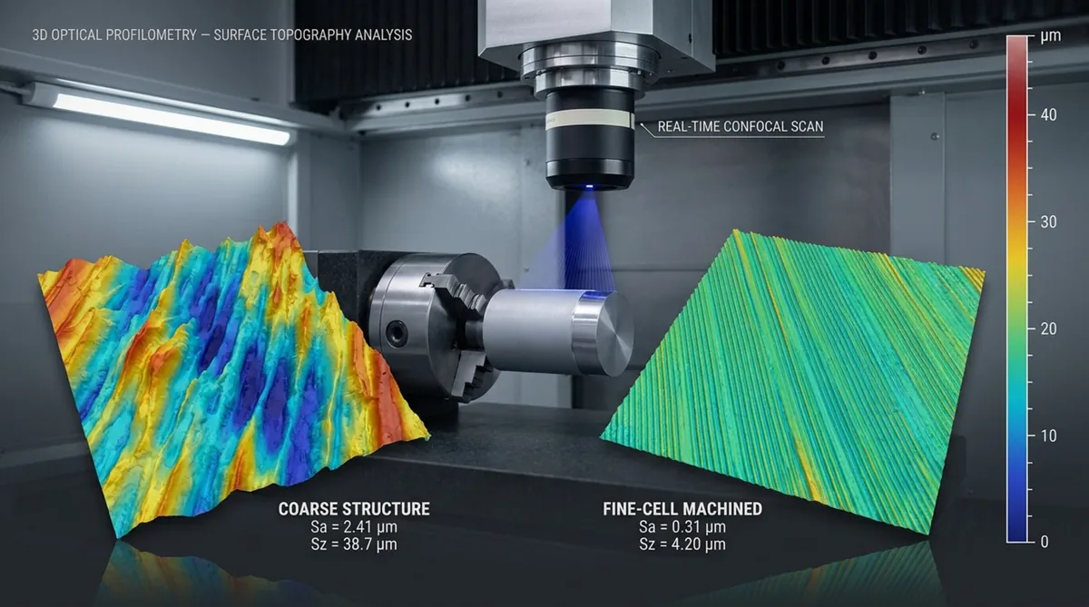
How does a fine cell size improve surface quality after machining? A fine cell size provides steady cutting resistance at the tool tip, which stops micro-tearing and prevents grain pullout. This uniform structure lowers surface roughness, holds tighter tolerances, and prevents edge breakout across both metallic alloys and structural foam cores.
What fine cell size means in a machined material
In materials science, a cellular microstructure is an internal grid of small sub-grains or solidified cells. Thin boundaries rich in solute elements, dislocation walls, or secondary phases separate these cells. You often see this structure in parts made by additive manufacturing, such as laser powder bed fusion (LPBF) and directed energy deposition (DED). It also appears in rapidly cooled alloys and closed-cell structural foam cores. In additively printed metals like 316L stainless steel, Inconel 718, and AlSi10Mg, rapid cooling creates cells that measure between 0.3 and 1.5 micrometers wide.
When engineers discuss fine cell size in machining, they refer to cell walls that are close together and spaced evenly through the stock. Standard wrought metals contain larger grains. Cellular materials have a much smaller internal network inside those grains. These closely spaced cell walls help control how the material yields and deforms under the cutting tool.
Why cellular microstructure affects the machined surface
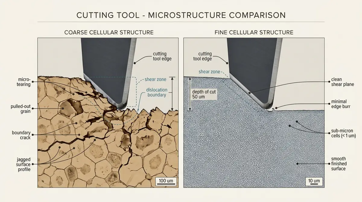
Machining is a process of controlled plastic deformation at high strain rates. As the cutting tool moves forward, it forces material into the primary shear zone. If the internal structure is coarse, the tool moves through alternating soft zones and hard boundaries. The shear angle changes quickly. These shifts create small tool vibrations, uneven cutting forces, and irregular spring-back behind the cutting edge.
A fine cellular structure changes this mechanical response. The cutting edge contacts hundreds of tiny cells at the exact same moment. When cell spacing is much smaller than the tool edge radius, the cutting force remains steady. The material shears away in clean layers rather than fracturing along weak crystal planes. This steady shear action prevents deep tool marks and reduces unwanted sideways material flow.
Fine cell size versus coarse cell size
The difference between fine and coarse cellular structures is clear under a microscope. In a coarse-celled material, the cutting tool drags through soft cell interiors before hitting thick, wide boundaries. This uneven force causes micro-tearing, grain pullout, and surface waviness. Coarse structures also show uneven elastic recovery, which makes it harder to hold tight dimensions.
A fine cellular structure spreads cutting forces across millions of small cells per cubic millimeter. The tool shears the material cleanly instead of plucking it out. This action creates a smooth finish with clear, regular feed lines. Edge burrs remain very small, and the material layer below the cut suffers far less strain damage. In PMI foam technology, an ultrafine cell structure like that found in Rohacell RIMA also prevents excessive resin absorption during downstream resin infusion and prepreg autoclave processes.
What Surface Quality Means After Machining
Surface quality after machining covers more than visual shine. It includes profile roughness, subsurface grain health, residual stress, and hidden micro-cracks. A shiny part can still hide high tensile stresses or micro-cracks. A thorough quality inspection evaluates profile peaks and valleys and verifies that the surface layer can support design loads.
High surface quality gives a component fewer stress points, a stable crystal structure, and exact geometric dimensions. These features dictate how well the component handles friction, fluid seals, protective coatings, and cyclic fatigue loads.
Surface roughness: Ra, Rz, and Sa
Engineers track surface finish using standardized roughness parameters. The most common metric is Ra, or average roughness. Ra calculates the arithmetic average of profile heights along a single evaluation length. Ra provides a quick check on process stability, but it can miss single deep scratches or sharp peaks that act as stress risers.
To capture these isolated flaws, engineers use Rz, which measures the average distance between the tallest peak and deepest valley across several sample lengths. For area-based inspections, Sa measures average areal roughness across an entire surface patch. A fine cellular structure lowers both Rz and Sa because the uniform material prevents local tearing and deep pits.
How surface quality affects fatigue, wear, sealing, and coating performance
The working life of a high-stress component depends directly on its surface integrity. Fatigue cracks typically begin at surface flaws. Small tool gouges, pulled grains, and micro-notches concentrate cyclic stress and start cracks. A fine-celled material creates a smooth, defect-free surface that delays crack initiation during high-cycle fatigue.
On sliding contact faces, surface peaks govern initial wear. Sharp peaks can pierce lubricating films, causing metal-to-metal contact, scuffing, and early adhesive wear. In gasketed joints, deep tool marks create micro-leak paths that fluids can pass through. When you apply thermal barrier coatings or PVD layers, a smooth substrate with minimal subsurface damage promotes strong mechanical bonding and stops coating flaking.
What Other Material Factors Affect Surface Quality?
Cell size is a primary driver of shear behavior, but it works alongside other metallurgical properties. Final surface finish depends on cell spacing, phase balance, bulk mechanical strength, and prior thermal conditioning. Overlooking these connected factors can reduce the surface finish benefits of a fine cell structure.
Overall machinability depends on the complete material system. Variations in grain orientation, secondary phases, and manufacturing flaws can cause uneven cutting, even when the base cell network is fine.
Grain size, phase distribution, and hardness
Grain size and cell size operate on two distinct physical scales. A single large grain often holds thousands of sub-micron cells. The Hall-Petch relationship shows that smaller grains increase yield strength and hardness by adding more grain boundary area. Higher hardness prevents the tool from sinking too deep into the workpiece, which limits smeared edges and heavy burrs.
Phase balance also alters the cutting action. In multi-phase alloys, different phases have contrasting hardness and thermal expansion rates. If hard secondary phases gather in large clusters, they can micro-chip the tool edge. A fine cell network keeps these phases small and evenly dispersed, which lowers tool wear and produces a uniform surface texture.
Porosity, inclusions, and defects from casting or additive manufacturing
Internal material voids degrade surface finish. In cast alloys, shrinkage pores, sand inclusions, and gas bubbles interrupt the path of the cutting tool. In 3D-printed metals, lack-of-fusion voids, un-melted powder, and keyhole pores cause identical issues.
When a cutting edge crosses an internal void, cutting resistance drops instantly. The tool then strikes the far wall of the void, creating an impact shock. This shock deflects the tool and can chip fragile cutting edges. Unsupported void edges can also fold over or tear, leaving rough pits that worsen both Ra and Rz values.
Why fine cell size must be evaluated with the complete process chain
Fine cell structures can change during post-processing. Additively manufactured parts often undergo stress relief or Hot Isostatic Pressing (HIP) to seal internal gas pores. However, excessive heat can dissolve fine cell boundaries and coarsen the grains.
Engineers must plan machining operations around the complete thermal schedule. Machining an as-printed part takes advantage of fine cells for clean shearing, but high residual stresses can cause the part to warp when released from its fixture. Conversely, machining after high-temperature homogenization can cause more smearing and tearing if the fine cell walls have dissolved. Similarly, when performing foam shape milling on rigid PMI cores, net-shape machining should occur after required heat treatment to maintain precise dimensional tolerances.
How Fine Cells Improve Material Removal
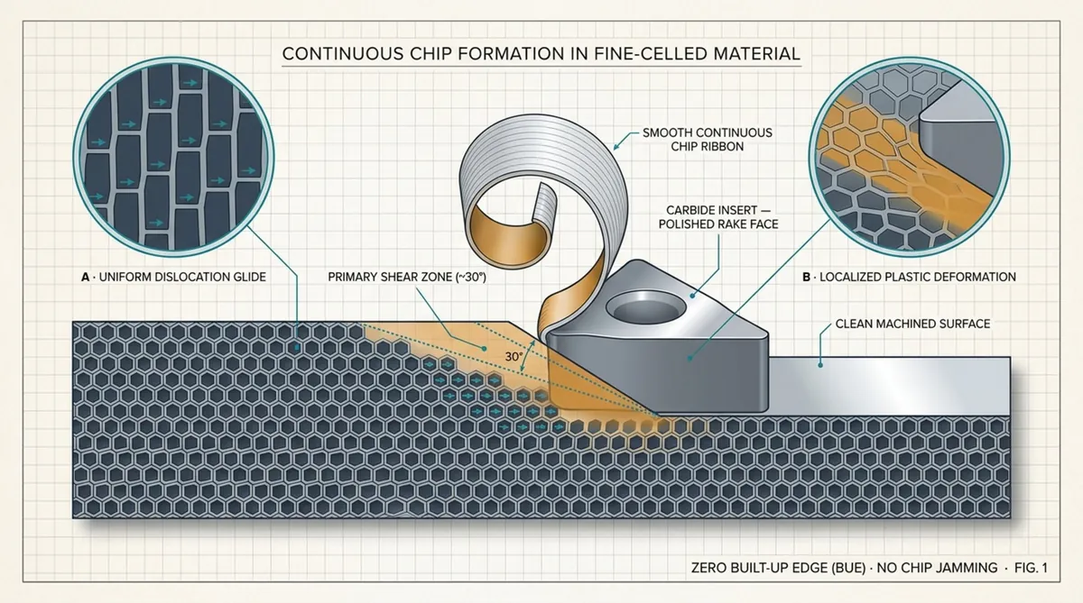
Material removal mechanics change when transitioning from a coarse structure to a fine cellular network. As the tool moves into the cut, plastic shear occurs through the generation and motion of crystal dislocations. Fine cell boundaries act as closely spaced obstacles that stop slip from concentrating along a few weak planes.
This controlled plastic flow distributes cutting energy evenly across the tool-chip interface. The cutting action shifts from erratic tearing to steady, micro-scale shearing. This provides a wider, more reliable machining window.
More uniform hardness and cutting resistance
Coarse structures present shifting micro-hardness levels as the tool edge moves from soft grain interiors to hard dendritic borders. These rapid shifts generate force spikes that can excite toolholder harmonics and cause chatter marks on the workpiece.
A fine cellular network keeps micro-hardness steady across the entire shear zone. Thousands of cell walls cross the shear plane simultaneously, providing near-constant cutting resistance. This smooth load keeps the tool path stable and produces uniform feed lines across the part.
Reduced tearing, smearing, and material pullout
Ductile materials often smear and weld to the cutting tool during machining. Under the compressive forces ahead of the tool edge, coarse grains can deform across wide areas before shearing off. This deformation creates heavy burrs, raised edge ridges, and torn cavities where grains pull free from the base metal.
Fine cell boundaries prevent this deep deformation by restricting dislocation travel. The material shears cleanly within a narrow, defined primary shear zone. Instead of flowing sideways under the tool edge, the metal moves smoothly up the tool face into the chip. This eliminates pullout cavities and leaves smooth profile valleys.
More consistent chip formation
Chip formation reveals cutting stability. Unstable cutting produces rough, heavily serrated chips that indicate cyclic shear collapse and periodic cracking. These fluctuating chip loads hammer the cutting edge, wear out tool geometry, and leave surface waviness on the component.
Fine-celled materials promote steady, continuous, or finely segmented chip ribbons. The dense cell network permits smooth plastic flow over the tool rake face. Predictable chip curling lowers the risk of chip jamming, chip recutting, and flank scoring, which protects the finished surface.
How Fine Cell Size Reduces Machining Defects
Machining defects weaken part strength and shorten service life. Edge chipping, micro-cracks, and open surface pores often start at weak spots in the microstructure. A fine cellular layout supports the material by spreading cutting loads across a dense network of internal boundaries.
By preventing local strain from growing into larger cracks during cutting, fine cells protect delicate geometries. This structural support is essential for thin walls, precision slots, and knife-edge contours that might otherwise deflect or break under cutting loads.
Reduced microcracking and edge chipping
When cutting brittle alloys or materials with hard inclusions, cutting shear stresses can exceed the local fracture strength. This stress drives micro-cracks down into the finished surface. In coarse structures, cracks spread quickly along cleavage planes or open grain boundaries, causing subsurface cracking and corner breakout as the tool exits the cut.
In fine-celled materials, any micro-crack that begins at the cutting edge quickly strikes a cell boundary. These dense, solute-rich walls blunt the crack tip, redirect its path, and absorb fracture energy through local deformation. This arrests micro-cracks before they reach deeper into the core structure.
Lower vibration-related surface waviness
Surface waviness is often caused by micro-vibrations at the tool-workpiece interface. When coarse grains tear irregularly, they create cyclic force spikes that disrupt spindle balance.
Fine-celled materials shear with low-amplitude, steady cutting forces that keep the machine system stable. Without the sharp impacts caused by coarse fracture, regenerative chatter is less likely to develop. The finished workpiece remains free from chatter facets, vibration tracks, and periodic surface waves.
Fewer pits, pores, and torn-out regions
Surface pits frequently appear when hard intermetallic phases or coarse inclusions pull out of the matrix instead of shearing cleanly. The resulting pockets disrupt surface flatness and act as sites for corrosion and mechanical failure.
A fine cellular network locks secondary phases tightly within the surrounding matrix. Instead of dislodging whole particles, the sharp tool shears straight through both the cells and the fine inclusions. The resulting surface shows a continuous plateau with far fewer pits than a coarse-grained material.
Which Machining Variables Determine the Final Surface Finish?
Microstructure dictates the ultimate surface finish potential, but machine settings determine how closely you reach that limit. While fine cells provide an ideal base, incorrect cutting parameters can still generate excessive frictional heat, tool rubbing, or chatter.
To realize the surface benefits of a fine cell structure, you must balance feed rate, spindle speed, tool geometry, and system rigidity. This balance ensures clean cutting rather than material burnishing.
Feed rate and chip load
Feed rate directly controls the theoretical height of feed cusps left by a radius tool. For an ideal cutting path, theoretical roughness is calculated using:
Rth = f² / (8 × R)
In this equation, f represents feed per revolution and R is the tool corner radius. However, if the feed rate drops too low, uncut chip thickness falls below the minimum chip thickness (hmin). When this occurs, the tool stops shearing and begins to plow and burnish the surface. Fine-celled materials have a lower hmin threshold, which allows lighter finishing feeds without causing surface smearing.
Cutting speed and spindle speed
Cutting speed dictates strain rates and shear zone temperatures. If cutting speed is too low, workpiece material can weld to the tool edge, forming a Built-Up Edge (BUE). When this unstable edge breaks away, it plucks material from the workpiece and scratches the cut path.
Increasing cutting speed generates moderate thermal softening in the primary shear zone, lowering cutting forces. Because fine cells resist tearing, higher surface speeds suppress BUE formation, allowing the tool to shear smoothly and generate a clean finish.
Machine rigidity, workholding, and chatter control
You can lose the benefits of a fine microstructure if the machining setup lacks stiffness. Machine flex, long tool overhangs, and loose clamping act like mechanical springs. They store and release cutting energy, creating regenerative chatter.
High structural rigidity ensures the programmed tool path matches the physical cut. Using solid clamping, balanced toolholders (such as hydraulic or shrink-fit chucks), and tuned mass dampers stabilizes the cutting zone. This setup rigidity is equally critical when Chem-Craft performs precision metal tooling and RTM molds milling to support closed-mold composite processing.
How to Preserve Fine-Cell Advantages During Machining
Taking full advantage of a fine-celled material requires tooling and operational parameters that protect the microstructure. Excessive heat from a dull edge or poor chip evacuation can cause dynamic recrystallization, coarsening the surface cells and degrading part quality.
Protecting the cellular structure requires coordinated tool selection, cooling, and toolpath programming. The objective is to shear material cleanly, clear chips rapidly, and keep cutting heat out of the finished workpiece.
Select cutting parameters for stable chip formation
Set feed rates safely above the minimum chip thickness while staying within your target Ra limits. Running step-by-step cutting trials will confirm the stable operating window for clean chip formation.
Use constant-engagement toolpaths, such as trochoidal milling or dynamic motion routines, to maintain an even chip load through corners. Preventing sudden spikes in radial engagement stops tool deflection and removes tool witness marks on contoured surfaces.
Use sharp, properly specified cutting tools
Tool sharpness is essential when machining fine-celled stock. Dull or heavily honed cutting edges increase compressive loads, crushing cells beneath the cut surface and creating deep residual stresses.
Select tools with small, controlled edge preparations, such as a light hone or polished micro-chamfer, paired with polished rake faces. Low-friction PVD coatings, such as TiAlSiN or diamond-like carbon (DLC), prevent chip sticking and maintain the sharp edge needed for micro-shearing. When processing structural foam cores, using sharp woodworking or plastic-milling cutters without lubricants prevents chemical contamination and preserves open surface cells for composite bonding.
Control heat and remove chips effectively
Controlling heat protects both surface finish and subsurface stability. Heat buildup in the shear zone causes thermal oxidation, tensile stresses, and unwanted phase changes. Trapped chips can get recut by the tool, gouging the finished surface.
Deliver high-pressure coolant directly into the tool-chip contact point to break chips and cool the cut. For sensitive dry operations, such as milling PMI foam sheets, high-volume vacuum extraction removes chips instantly and prevents friction-induced heating on machined faces.
How to Measure the Surface-Quality Benefits of Fine Cells
Evaluating the surface benefits of fine-celled materials requires high-resolution metrology tools. A manual fingernail check or basic workshop gauge cannot detect sub-micron differences between a torn surface and a clean shear plane. Reliable verification requires calibrated contact and optical instruments.
Proper metrology records both general roughness trends and isolated micro-flaws. Tracking these metrics over production runs connects cellular refinement directly to part quality.
Ra and Rz measurements with a stylus profilometer
Stylus profilometry is an established standard for checking machined surfaces. A diamond stylus, typically with a 2 to 5 micrometer tip radius, traces across the surface under a controlled contact force. The instrument records vertical stylus movement to calculate profile heights.
To measure fine-celled surfaces accurately, match the cutoff filter length (λc) and evaluation length to the tool feed pitch. On a fine-celled part, the profile will show regular, shallow peaks and valleys. Rz values will remain close to the average Ra value, confirming that the tool sheared through the material without grain pullout or deep micro-voids.
3D optical measurement of Sa, Sz, and surface defects
While stylus tracing provides valuable linear data, a single 2D trace can miss nearby micro-pits or cracks. Non-contact 3D optical instruments, including Coherence Scanning Interferometry (CSI) and confocal microscopy, capture complete areal topography without touching the part.
Areal parameters such as Sa (average surface height) and Sz (maximum peak-to-valley height) give a complete view of surface texture. 3D height maps clearly reveal feed cusp tearing, side-flow ridges, and edge breakout. Fine-celled parts consistently show uniform machining marks, low valley depths, and clean edges.
Advanced manufacturing cells also integrate non-contact optical sensors directly into CNC spindles. These sensors evaluate surface finish while the part remains clamped in its fixture. Connecting this feedback to real-time machine controllers allows immediate feed adjustments to compensate for local cell size shifts, ensuring uniform surface quality across complex components. Contact our technical team at Chem-Craft to discuss material selection, foam core machining parameters, and tooling requirements for your composite manufacturing operations.