How do composite engineers successfully bond PMI foam to carbon fiber skins in high-performance sandwich structures? Achieving a reliable bond requires matching cure kinetics to core thermal limits, removing absorbed moisture before lay-up, and controlling consolidation pressure to prevent cell collapse. At Chem-Craft, we supply precision-machined ROHACELL® structural foam cores and processing guidance to ensure your composite manufacturing process meets strict structural requirements.
What Are the Key Rules for Bonding PMI Foam to Carbon Fiber?
Match the adhesive to the PMI core and carbon fiber resin system
The adhesive serves as both a chemical bridge and a load-transfer medium across the interface. A compatible adhesive, typically a toughened epoxy, must match the cure chemistry of both the carbon prepreg matrix and the polymethacrylimide (PMI) core. This matching prevents phase separation and weak boundary layers at the joint. The adhesive system must also cure at a rate that aligns with the laminate cycle so that neither component undergoes thermal degradation from unmanaged exothermic heat.
Uncontrolled chemical reactions can plasticize the surface cells of the core. Selecting an adhesive with an engineered curing agent prevents unreacted monomers from migrating into the outer cell walls, which would otherwise degrade core shear strength. Process testing must also verify that adhesive volumetric shrinkage remains within engineering requirements to minimize residual shear stress during cool-down.
Follow the foam manufacturer’s processing limits
Different PMI foam technology grades provide distinct density ratings, temperature thresholds, and creep resistance. Exposing a general-purpose grade to high-temperature autoclave cycles intended for aerospace grades like ROHACELL® WF or ROHACELL® XT can lead to rapid softening, internal cell gas expansion, and core distortion. Engineering teams must always consult the official technical data sheets for maximum cure temperatures and pressure allowances.
These material limits also dictate pre-cure thermal preparation. PMI structural foam cores absorb atmospheric moisture when exposed to ambient shop air. If you cure a wet core at temperatures above 100°C, the trapped moisture vaporizes into steam, creating blown skins and extensive disbonds. Conducting a standardized drying cycle in a circulating-air oven-typically at 135°C for at least four hours-removes this moisture prior to lay-up.
Control bond-line thickness and avoid excessive adhesive weight
Sandwich construction aims to maximize bending stiffness while keeping total weight minimal. An excessively thick bond line undermines this goal. Structural bond lines generally perform best at thicknesses between 0.10 mm and 0.25 mm. Exceeding this thickness adds dead weight without improving structural integrity, while creating unreinforced resin pockets that are prone to microcracking under cyclic mechanical stress.
Conversely, an adhesive layer that is too thin causes dry areas and cannot transfer shear forces from the carbon face sheets into the core. Using supported film adhesives with lightweight non-woven carriers or scrims helps maintain an even bond-line thickness across complex shapes. These carriers prevent total resin squeeze-out under pressure and promote consistent meniscus fillet formation along the cut cell edges.
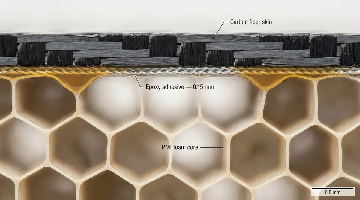
Prevent resin starvation, resin pooling, and core crush
Resin management requires balancing resin viscosity and consolidation pressure. If you apply dry fabric or uncured prepreg directly onto unsealed structural foam cores, low-viscosity resin flows into the open surface cells. This action starves the carbon fiber plies of resin, resulting in dry laminate areas while simultaneously adding unwanted resin weight to the foam core.
Consolidation pressure must never exceed the compressive yield strength of the foam at the selected cure temperature. PMI foam softens as it approaches its glass transition point. Pressure levels that are safe at ambient temperatures can crush the cellular structure at 180°C. Applying multi-stage pressure cycles and using compatible surface sealers protects the core from crushing during consolidation.
Maintain compatible cure temperature, pressure, and time
Manufacturing high-performance sandwich structures requires precise coordination of thermal and pressure cycles. The adhesive must reach its minimum viscosity point to wet both substrates thoroughly before cross-linking, all while the core maintains dimensional stability. If the ramp rate is too fast, the outer carbon plies cure early, preventing proper volatile evacuation from the core interface.
A controlled ramp rate of 1°C to 2°C per minute establishes uniform thermal distribution through the entire panel. This gradual heating reduces thermal shock and limits internal shear stress caused by differences in thermal expansion. It also aligns the peak viscosity window of the adhesive with the mechanical pressure hold.
Use uniform pressure across the entire sandwich panel
Uneven consolidation pressure causes localized core crushing, variable bond-line thickness, and laminate bridging. Vacuum bagging arrangements must eliminate bridging over steps, edge chamfers, and tight radii. Bridging leads to low-pressure zones that trap air and volatiles, while adjacent sections take excessive pressure that can crush the underlying foam cells.
Using semi-rigid caul plates or elastomeric pressure intensifiers distributes force evenly over complex geometries. Proper bag pleating ensures that autoclave or atmospheric pressure acts directly normal to the surface, delivering uniform consolidation across the entire bond line.
What Bond-Line and Core-Design Rules Prevent Failure?
Match core density and thickness to compressive and shear loads
Reliable sandwich construction begins by selecting the right core grade for the applied stress profile. Higher-density PMI foam grades provide superior compressive strength and shear stiffness, making them suitable for localized load introductions and high-shear zones. Lower-density grades maximize weight savings in broad, flexure-dominant panels. Selecting an insufficient density can cause core shear fracture during bending loads.
Engineers must calculate the transverse shear stress distribution between the carbon fiber skins across the operating envelope. While increasing core thickness increases the structural moment of inertia with minimal weight penalty, the core material must possess sufficient shear modulus to prevent longitudinal splitting along the neutral axis during panel deflection.
Design edge closeouts and hard points for concentrated loads
Structural foam cores distribute distributed surface loads efficiently, but they cannot support high concentrated point loads from mechanical fasteners. Tightening a bolt directly through an unreinforced sandwich panel crushes the local cellular matrix and causes skin delamination. High-load attachment points require solid laminate inserts, metallic bushings, or localized high-density potting compounds.
Edge closeouts using monolithic carbon lay-ups, potted borders, or machined perimeter frames protect the foam boundary from environmental exposure and mechanical impact. These closeout designs transition loads directly into the carbon skins rather than concentrating stress on the foam edges.
Prevent peel stress at panel edges and inserts
Adhesive bonds between carbon fiber skins and PMI cores exhibit high shear and tensile strength but lower resistance to out-of-plane peel forces. At unsupported panel edges or cutouts, normal loads can peel the thin carbon skin away from the core. Once initiated, peel defects propagate rapidly along the bond line under cyclic service conditions.
To reduce peel stress, chamfer the core perimeter at a shallow angle, typically between 20 and 30 degrees. This allows the continuous carbon fiber plies to taper down and consolidate directly onto the opposite skin or perimeter tooling, sealing the core inside a continuous structural envelope.
Avoid sharp transitions that create local stress concentrations
Abrupt changes in core thickness, right-angle cutouts, and steep chamfers create sharp stiffness mismatches. Under dynamic loading, these geometric steps concentrate high shear stress directly at the adhesive line, initiating localized disbonding.
Core geometry changes should incorporate generous radii and gradual tapers. Chem-Craft supports this requirement through high-precision foam shape milling and contouring services that eliminate sharp transitions. Stepping the carbon prepreg plies along the core ramps ensures a progressive change in structural stiffness and prevents peak stress concentrations.
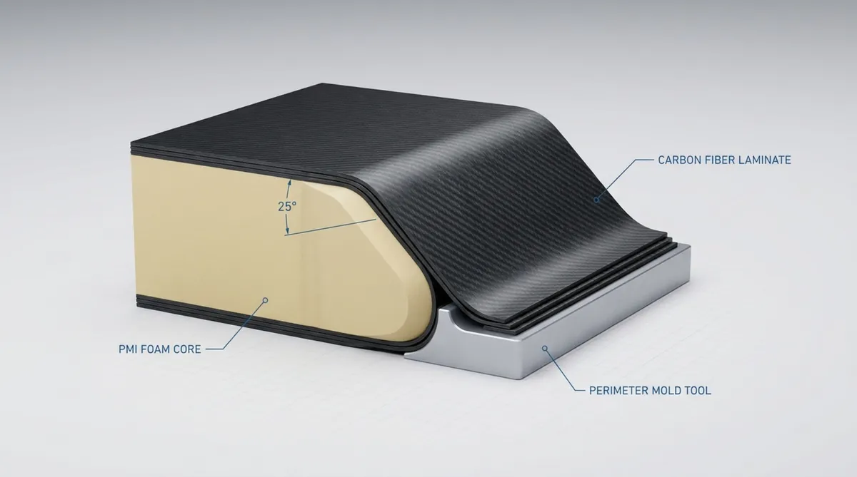
Account for thermal expansion differences between foam, resin, and carbon fiber
Carbon fiber exhibits a near-zero or slightly negative coefficient of thermal expansion (CTE) along the fiber axis, whereas PMI foam cores and epoxy resins expand and contract significantly with temperature changes. This CTE mismatch generates residual thermal stresses as the part cools down from elevated cure temperatures.
Ignoring these expansion differences leads to panel warpage, microcracking within the resin, or premature shear failure at the interface. Designers reduce residual stress by choosing toughened adhesives with higher elongation capabilities, maintaining symmetric and balanced carbon ply lay-ups, and enforcing controlled cooling rates after curing.
How Should PMI Foam and Carbon Fiber Skins Be Prepared?
Inspect foam density, thickness, flatness, and surface condition
Quality control begins before core lay-up. Incoming PMI foam sheets must be inspected for dimensional accuracy and surface integrity. Measure thickness across the sheet using non-marring instruments, as small thickness variations cause uneven pressure distribution during autoclave processing.
Surface conditions require careful evaluation. Surface grooves, wire-cut steps, or handling impressions can trap air pockets that standard adhesive films cannot fill. For tight engineering tolerances, Chem-Craft provides horizontal cutting on structural foam sheets down to 1 mm thickness with tolerances up to 0.1 mm, delivering uniform surfaces ready for lamination.
Prepare carbon fiber skins without damaging the laminate
In secondary bonding operations where pre-cured carbon skins are joined to PMI foam, surface preparation dictates ultimate joint strength. The goal is to raise surface energy and remove contaminants without breaking the structural carbon fibers. Uncontrolled hand sanding can damage load-bearing plies and reduce laminate tensile strength.
The standard industry approach uses a peel ply co-cured on the bonding face of the carbon skin. Stripping the peel ply immediately before bonding exposes a clean, textured surface ideal for mechanical interlocking. If light abrasion is required, use fine non-metallic abrasive media under controlled pressure, followed by verified cleaning procedures.
Remove dust, release-agent residue, moisture, and contamination
Surface contamination is a primary cause of adhesive failure and poor interfacial strength. Machining PMI foam produces fine, electrically charged particles that settle inside the exposed open cells. If left in place, this dust prevents the adhesive from wetting the actual cell walls, resulting in a weak boundary layer.
Remove particulate debris using industrial vacuum systems followed by dry, oil-free compressed air. For maximum bond performance, running a needle roller across the foam surface creates microscopic mechanical anchors that increase bond toughness. Cured composite skins must also be verified free of silicone and fluoropolymer mold release agents using approved solvent wiping techniques.
Use abrasion and solvent cleaning only when approved by the supplier
PMI foam shows good solvent resistance compared to many other polymers, but aggressive chemicals like acetone or chlorinated solvents can still damage cell structures if applied incorrectly. Always verify chemical compatibility before exposing the core to cleaning agents.
Direct mechanical abrasion on raw PMI foam must be tightly controlled. Hand-sanding raw foam tears open the thin cell walls and leaves ragged fragments that compromise the bond interface. When cleaning cured carbon skins with solvents, allow complete flash-off and drying time to prevent solvent entrapment inside the sandwich assembly.
Control storage temperature, humidity, and adhesive shelf life
Epoxy paste and film adhesives require strict cold-storage protocols to prevent premature advancement. Allowing film adhesive to sit at room temperature reduces its tack and flow characteristics, hindering its ability to wet the porous surface of the foam core during the cure cycle.
Moisture control in the processing cleanroom is equally critical. Because PMI foam absorbs humidity from ambient air, material stored outside protective packaging collects moisture. When exposed to high cure temperatures, this moisture turns to steam, creating unbonded pockets. Store dried core materials in moisture-barrier aluminum bags, and log all cumulative cleanroom out-time to verify that drying limits are not exceeded.
Which Adhesive and Surface Treatments Improve Bond Strength?
Why adhesive compatibility matters more than maximum strength alone
Selecting an adhesive based solely on bulk tensile strength from a data sheet can result in joint failure. An adhesive that cures into an overly stiff, brittle matrix cannot accommodate the strain differentials that occur as thin carbon skins bend over an elastic foam core. This mismatch produces high edge shear stresses and early cracking.
Sandwich engineering requires a balance of shear modulus, peel strength, and fracture toughness. Toughened adhesives absorb dynamic energy, bridge microcracks, and accommodate thermal expansion strains, outperforming brittle high-strength adhesives under operational fatigue loads.
Epoxy adhesives for high-strength structural sandwich panels
Epoxy resins remain the industry standard for bonding carbon fiber to PMI foam cores in aerospace, automotive, and industrial composite applications. Epoxy matrices exhibit low volatile emission during curing, minimal cure shrinkage, and excellent resistance to hot-wet operating environments.
Elastomer-modified or thermoplastic-toughened epoxies provide superior service at the carbon-foam boundary. They support thin carbon skins against localized micro-buckling and transfer alternating loads into cores such as ROHACELL® IG-F or ROHACELL® RIMA without developing interfacial fatigue cracks.
Film adhesives for controlled coverage and low void content
Structural film adhesives provide distinct advantages in sandwich panel manufacturing. Supplied at calibrated areal weights-typically between 100 and 200 g/m²-they eliminate the application inconsistencies, air entrapment, and thickness variations common with manual paste spreading.
During the thermal cycle, film adhesives undergo a controlled drop in viscosity, flowing into the surface cells of the PMI foam just enough to establish a secure mechanical lock without excessive weight uptake. The internal scrim cloth maintains uniform separation between the carbon plies and the core across the entire panel.
Paste adhesives for gaps, repairs, and complex geometries
While film adhesives excel on uniform surfaces, two-part structural paste adhesives are essential for complex tooling contours, core splice joints, closeout filling, and structural repairs. Thixotropic paste formulations resist sagging on vertical tool faces and fill dimensional tolerances where film cannot make contact.
Paste systems should be dispensed through automated meter-mix equipment or static-mixing nozzles to avoid entraining air bubbles. When filling core splices or installing inserts, select low-exotherm paste formulations to avoid localized heat spikes that could damage adjacent PMI cell walls.
When primers and adhesion promoters improve reliability
In applications subjected to sustained high temperatures or fluid immersion, applying a compatible liquid primer improves joint reliability. Low-viscosity primers penetrate open surface cells more readily than high-viscosity prepreg resins, sealing the cell walls and creating a chemically active surface for the adhesive film.
Surface activation methods such as atmospheric plasma or corona treatments can also be applied to cured carbon skins. These treatments break down trace organic residues and introduce functional polar groups to the laminate surface, improving adhesive wetting and long-term environmental durability.
How Does Autoclave and Vacuum-Bag Processing Affect the Bond?
Autoclave pressure, heat-up rate, and cure-temperature control
Autoclave processing produces high consolidation quality and low void content, but cycle parameters must remain within the physical limits of the cellular core. Certain structural grades like ROHACELL® can be processed at temperatures up to 180°C and pressures up to 0.7 MPa when heat-treated correctly, but exceeding these thresholds leads to core collapse.
The heating rate must be managed to avoid runaway exothermic reactions in thick carbon laminates. A steady ramp rate of 1°C to 2°C per minute allows balanced heat transfer through the tooling, carbon skins, and insulating foam core. This gradual ramp ensures the adhesive stays in its low-viscosity wetting window long enough to secure the bond before hardening.
Preventing PMI cell damage during heating and pressurization
Protecting the cellular structure requires tailoring the autoclave pressure profile to the foam’s temperature-dependent compressive yield strength. Through pressure staging, full consolidation pressure is applied at lower temperatures to debulk the carbon plies and evacuate air, and is then moderated before the core reaches its softening point.
Tooling design also safeguards core geometry. Machined metal edge stops or perimeter shims placed on the tool frame support caul plates at the exact design thickness. These mechanical stops bear the excess autoclave loads, preventing over-pressurization of the internal PMI core.
Managing volatile release, trapped air, and adhesive bleed
Consolidation cycles must allow entrapped air and volatile reaction gases to escape before the adhesive gels. If bagging arrangements seal the vacuum paths prematurely, these gases become trapped along the bond line, forming unbonded voids and porous areas.
Vacuum channels should remain open without drawing necessary resin out of the carbon plies. Excessive resin bleed starves the laminate and reduces structural properties. Using release films with calculated perforation patterns, combined with edge-breathing arrangements, releases trapped gases while maintaining proper resin content in the structural plies.
Using caul plates, breather layers, and release films correctly
The bagging stack determines how thermal energy and mechanical pressure reach the sandwich part. Precision caul plates made of aluminum or carbon composite bridge localized tooling gaps, smooth out bag wrinkles, and prevent the vacuum bag from forcing plies into core recesses.
A continuous breather layer placed above the caul plate maintains an unrestricted evacuation path to the vacuum ports. Perforated or solid release films positioned directly against the composite laminate protect surface finish quality and prevent the structural adhesive from migrating into the breather materials.
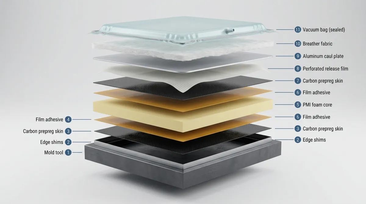
When out-of-autoclave bonding is suitable
Out-of-autoclave (OOA) and vacuum-bag-only (VBO) processing methods produce high-quality sandwich structures while lowering tooling and capital expenses. Because VBO processing relies solely on atmospheric pressure (approximately 0.1 MPa), the risk of crushing lower-density PMI cores is minimized.
VBO methods are widely used for marine structures, wind energy components, and industrial enclosures. These processes require prepregs and film adhesives engineered with internal dry evacuation channels, allowing air to escape under vacuum before the matrix liquefies and cures.
What Defects Occur When PMI Foam Is Bonded Incorrectly?
Voids and disbonds caused by trapped air
Interfacial voids break the load path between the structural skin and the core. They stem from insufficient debulking, using low-tack prepregs that bridge surface contours, or losing vacuum integrity during the initial thermal ramp. Trapped air blocks physical contact between the adhesive and the substrates.
Under compressive or flexural loads, a carbon skin over a disbonded pocket lacks stabilization against buckling. The skin can buckle prematurely, driving dynamic shear cracks through adjacent adhesive fillets and causing progressive panel failure.
Core crushing caused by excessive pressure or unsupported areas
Core crush happens when external consolidation forces exceed the compressive strength of the heated foam. This defect appears as localized surface depressions, panel thickness variations, or internal shear collapse. In extreme cases, the cellular matrix collapses completely, permanently altering the geometry of the part.
Crush defects are frequently localized. Stiff carbon prepreg plies can bridge across tool recesses, concentrating autoclave pressure onto adjacent foam sections. This localized compression creates severe stress concentrations and ruins dimensional accuracy.
Resin uptake that increases weight and reduces design efficiency
Although PMI foam features a closed-cell morphology, cutting and milling operations expose the outermost layer of half-cells. If an unsealed core meets low-viscosity resin under high pressure, resin flows directly into these surface cavities.
Excessive resin uptake adds unnecessary weight without contributing to structural performance. In weight-critical aerospace and automotive parts, this extra resin reduces operational efficiency and can leave surrounding carbon plies resin-starved.
Delamination caused by contamination or poor surface preparation
When sandwich failure exhibits clean adhesive separation from the skin or core rather than cohesive foam fracture, contamination is typically the root cause. Parting agents, silicone residues, handling oils, and machining dust act as release barriers on the bonding surface.
Contaminated bonds often pass initial visual inspection because the components appear consolidated. However, the interface lacks mechanical toughness. Operational vibration, environmental moisture, and thermal cycling quickly break down the interface, leading to widespread skin-to-core separation.
Blistering and bond failure after thermal cycling
Composite assemblies deployed in aerospace or transport applications experience severe temperature fluctuations. If residual moisture remains trapped inside the PMI core cells, elevated operating temperatures vaporize the moisture into steam.
This internal vapor pressure, compounded by CTE differences between the carbon skins and the core, generates interfacial blisters. The carbon skin lifts away from the core, compromising the structural integrity of the sandwich construction and leaving it vulnerable to environmental ingress.
How Can Bonded PMI Sandwich Panels Be Inspected and Tested?
Visual inspection for wrinkles, gaps, resin pooling, and surface defects
Visual inspection provides an immediate assessment of visible laminate quality. Using directed surface lighting, inspectors check the cured carbon skin for ply distortion, surface wrinkles, edge-bridging defects, and local depressions indicating underlying core crush.
Perimeter closeout areas should be inspected for excess resin pooling, dry fibers, and alignment gaps. Surface distortions and localized resin accumulations frequently indicate irregularities in cure temperature or bagging pressure control.
Ultrasonic testing for voids, disbonds, and delamination
Non-destructive ultrasonic testing is the standard method for verifying sandwich bond lines. Through-transmission and phased-array ultrasonic systems detect changes in acoustic impedance as sound waves pass through the carbon skins, adhesive layers, and core material.
Because the cellular structure of PMI foam attenuates high-frequency signals, testing is typically performed using lower transducer frequencies, generally between 0.5 MHz and 2.25 MHz. Ultrasonic C-scans map the size, depth, and precise location of internal voids, disbonds, and core cracks without altering the component.
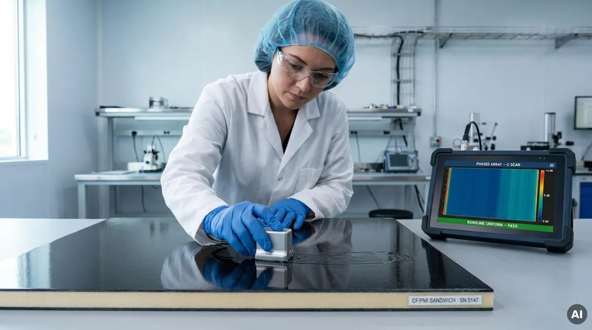
Tap testing for rapid field inspection
Tap testing serves as an efficient field-inspection tool for detecting near-surface disbonds in sandwich panels. A trained technician uses an inspection hammer or automated tap device to impact the carbon skin systematically, listening to the acoustic response.
A clear, crisp acoustic response indicates a well-bonded skin supported by the underlying foam core. A dull, hollow tone indicates an internal void or disbond where the skin is vibrating freely. While tap testing is limited to larger, near-surface defects, it remains an effective method for rapid maintenance assessments.
Flatwise tensile and core shear testing
Destructive mechanical testing of representative witness coupons provides quantitative validation of bond-line strength. The flatwise tensile test, governed by ASTM C297, measures the ultimate bond strength normal to the sandwich plane. In a well-designed joint, failure occurs cohesively within the PMI foam core rather than adhesively at the bond line.
Core shear testing, conducted via beam flexure per ASTM C393, measures the assembly’s resistance to horizontal shear forces across the skin-to-core interface. This test confirms that the adhesive has wetted the cut cell walls sufficiently to transfer design shear stresses without interfacial slippage.
Peel, compression, impact, and fatigue testing
Comprehensive qualification programs evaluate sandwich performance under varied environmental and dynamic loads. Climbing drum peel tests (ASTM D1781) measure the mechanical energy required to strip the carbon skin from the core, identifying flaws in surface preparation or adhesive toughness.
Long-term service life is verified through flatwise compression and cyclic fatigue testing that simulate operating life cycles. Low-velocity impact testing evaluates resistance to tool drops and runway debris, checking whether localized surface impacts cause hidden core damage or subsurface disbonding.
Which Bonding Rules Should Be Verified Before Production?
Confirm adhesive and foam compatibility with supplier technical data
Before launching serial production, engineering teams must confirm the chemical, thermal, and mechanical compatibility of the adhesive, carbon prepreg, and PMI core. Technical data sheets must be cross-referenced to verify that cure cycles, reaction kinetics, and operating limits align without exceeding core thresholds.
Direct technical consultation with material specialists clarifies nuances such as volatile release rates and adhesive fillet behavior. Working with certified materials from experienced distributors like Chem-Craft ensures the selected foam grade aligns directly with your composite manufacturing process.
Verify cure temperature, pressure, bond-line thickness, and open time
All processing parameters must be validated experimentally rather than assumed from theoretical models. Place calibrated thermocouples throughout pre-production tooling trials to map the thermal gradient across the carbon skins and core center. This ensures the entire bond line achieves the target cure temperature without experiencing thermal spikes.
Process windows must define adhesive open time, shop environmental limits, thermal ramp rates, and pressure holds. Documenting these parameters prevents shop-floor variations from causing core crushing or premature adhesive gelation.
Inspect representative coupons before releasing the design
Engineering designs should never be released to serial production solely on simulation data. Representative trial coupons must incorporate the planned carbon lay-up, core thickness, edge chamfers, and closeout features to validate manufacturing feasibility on real parts.
Subject these pre-production test articles to both ultrasonic NDT inspection and destructive mechanical testing. Achieving 100% cohesive foam failure during flatwise tensile and shear evaluations confirms that the tooling, materials, and process instructions are production-ready.
Document acceptance criteria for voids, disbonds, and core damage
Clear defect acceptance limits must be incorporated into engineering drawings and quality specifications. These criteria define the maximum allowable single void area, total accumulated void percentage per panel, and minimum separation distances between adjacent defects.
Quality plans must also specify allowable limits for edge deviations, core-crush depth, and core splice gap tolerances. Concrete numerical criteria eliminate subjective evaluations and ensure prompt disposition of out-of-spec components.
Use qualified procedures for safety-critical composite structures
Primary aerospace structures, specialized automotive components, and marine hulls require documented qualification and batch traceability. Every stage of manufacturing must be recorded in serialized work orders, including cleanroom humidity readings, adhesive out-time tracking, autoclave run profiles, and non-destructive testing reports.
Standardized, qualified process procedures ensure high consistency across shifts and production runs. If you need technical assistance in selecting the optimal structural foam core or setting up your bonding parameters, contact our engineers at Chem-Craft to review your composite application requirements.